


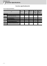
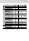
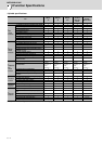
2 Specifications
MITSUBISHI CNC
2 - 66
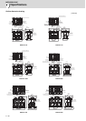
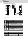
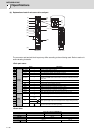
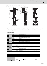
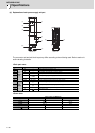
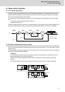
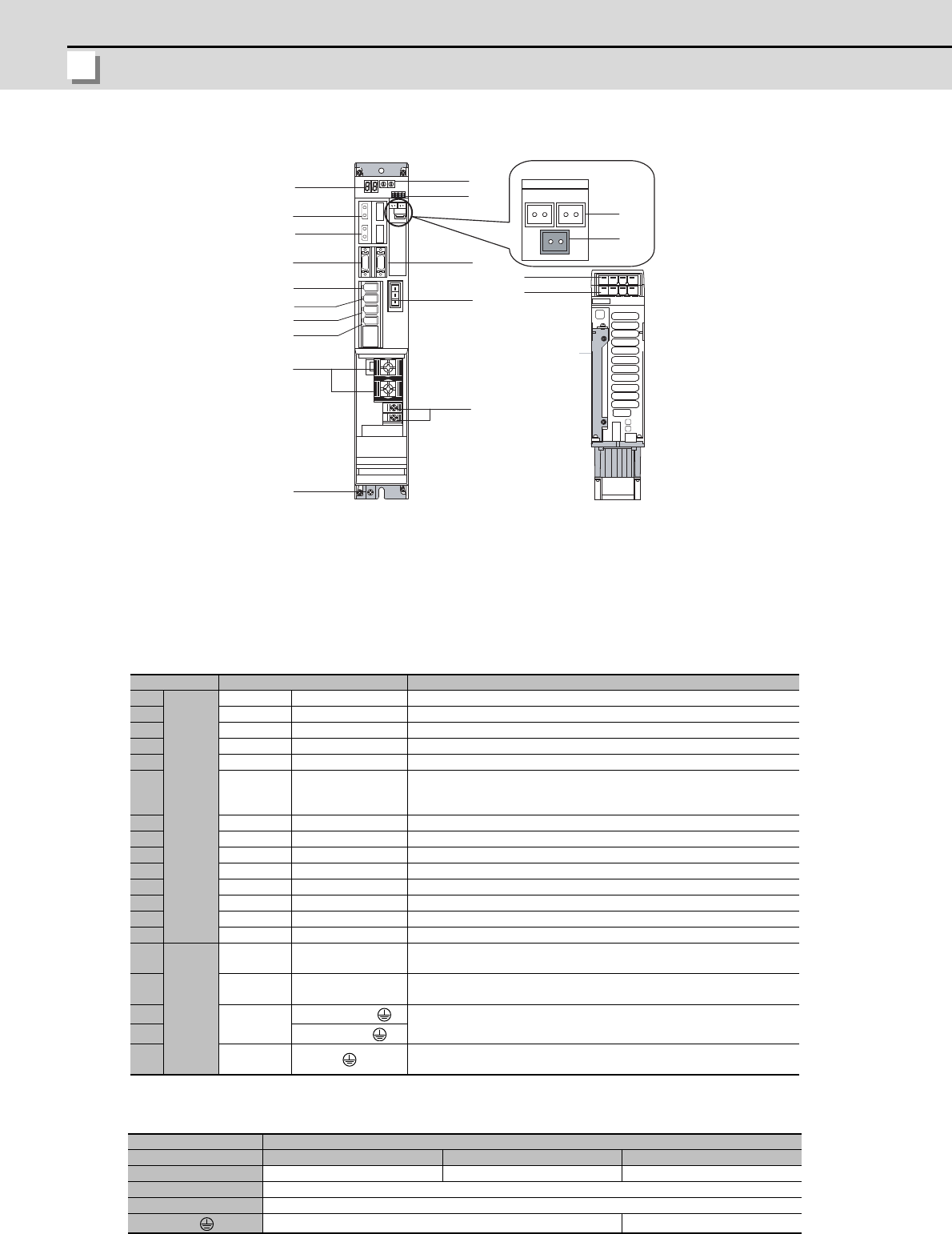
(b) Explanation of each 2-axis servo drive unit part
The connector and terminal block layout may differ according to the unit being used. Refer to each unit
outline drawing for details.
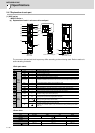
<Each part name>
<Screw size>
Name Description
(1)
Control
circuit
LED --- Unit status indication LED
(2) SWL,SWM --- Axis No. setting switch (L,M axis)
(3) SW1 --- Unused axis setting switch (L, M axis)
(4) CN1A --- NC or master axis optical communication connector
(5) CN1B --- Slave axis optical communication connector
(6) BTA,BTB ---
For connecting converged battery unit
Both BTA and BTB are the same function, and they are internally connected
each other.
(7) BT1 --- For connecting battery built-in drive unit ER6V-C119B
(8) CN9 --- Maintenance connector (usually not used)
(9) CN4 --- Power supply communication connector
(10) CN2L --- Motor side detector connection connector (L axis)
(11) CN3L --- Machine side detector connection connector (L axis)
(12) CN2M --- Motor side detector connection connector (M axis)
(13) CN3M --- Machine side detector connection connector (M axis)
(14) CN20 --- Motor brake/dynamic brake control connector (Key way: X type)
(15)
Main
circuit
TE2
L+
L-
Converter voltage input terminal (DC input)
(16) TE3
L11
L21
Control power input terminal (single-phase AC input)
(17)
TE1
MU, MV, MW,
Motor power supply output connector(3-phase AC output), Motor grounding
(18)
LU, LV, LW,
(19) PE
Grounding terminal
Use TE1 connector for the motor grounding.
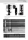
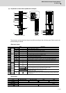
2-axis servo drive unit MDS-DH-V2-
Type 1010 to 4040 8040, 8080 8080
Unit width (mm) 60 90 120
(15) TE2 M6×16
(16) TE3 M4×12
(19)
M4×12 M5×12
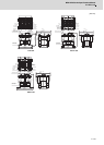
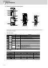
MDS-DH-V2
Bottom view
(2)
(3)
(4)
(5)
(1)
(9)
(12)
(14)
(17)
(15)
(8)
(10)
(11)
(13)
(6)
(7)
(16)
(18)
(19)