5 - 23
MDS-D/DH Series Specifications Manual
5-1 Servo options
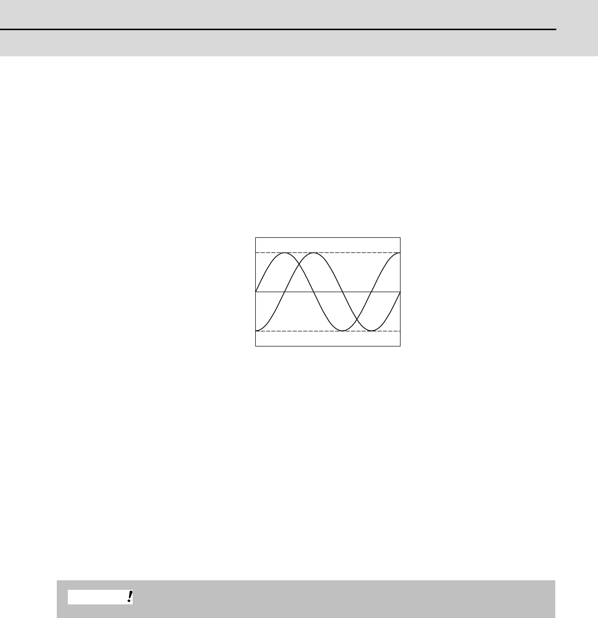
(b) SIN wave output (using MDS-B-HR)
When using a relative position detector that the signal is the SIN wave output, the detector output signal
is converted in the detector conversion unit (MDS-B-HR), and then the signal is transmitted to the drive
unit in the serial communication. Select a relative position detector with A/B phase SIN wave signal that
satisfies the following conditions. For details on the specifications of MDS-B-HR, refer to the section
"MDS-B-HR".
<Detector output signal>
- 1Vp-p analog A-phase, B-phase, Z-phase differential output
- Output signal frequency 200kHz or less
- Combination speed / rotation speed
In use of linear scale:
Maximum speed (m/min) = scale analog signal frequency (m) x 200,000 x 60
In use of rotary encoder:
Maximum rotation speed (r/min) = 200,000 / numbers of encoder scale (1/rev) x 60
An actual Maximum speed/ rotary speed is limited by the mechanical specifications and electrical
specifications, etc. of the connected scale, so contact the manufacture of the purchased scale.
- Division number 512 divisions per 1 cycle of signal
In use of linear scale:
Minimum resolution (m) = scale analog signal frequency (m) / 512
In use of rotary encoder:
Minimum resolution (pulse/rev) = numbers of encoder scale (1/rev) x 512
The above value does not guarantee the accuracy of the system.
0.5
-0.5
0
A phase B phase
Voltage [V]
A/B phase output signal waveform during forward run
Time
CAUTION


