


5 - 19
MDS-D/DH Series Specifications Manual
5-1 Servo options
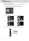
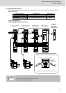
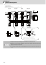
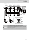
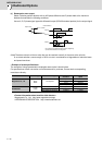
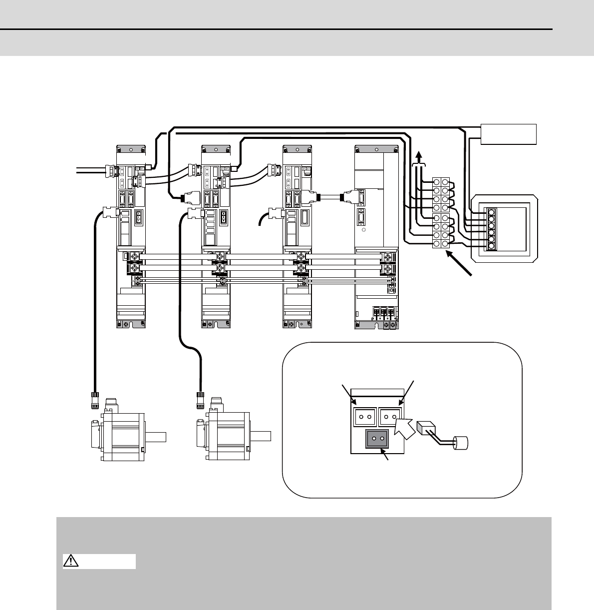
(b) MDS-D/DH-V1/V2 Series connected in parallel
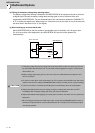
1. 24V power for DO output must always be turned ON before the NC power input.
2. Spindle drive unit has no battery voltage drop warning function. Wiring to CN9 of drive unit must be
always connected to servo drive unit.
3. The total length of battery cable (from the battery unit to the last connected drive unit) must be 3m
or less.
BTA
BT1
1 2
1 2 1 2
BTB
DOCOM
DO(ALM)
LG
+5V
LG
BT
MDS-BTBOX-36
DG24
DG23
CN9
BTB BTB
DG2
L+
L-
+24V
RG
(MDS-D/DH-V1) (MDS-D/DH-V2) (MDS-D/DH-SP) (MDS-D/DH-CV)
For cell battery
Connect the battery unit with BTA or BTB.
Connect either the battery unit or the cell battery.
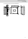
Servo drive unit
Battery connector connection part magnified figure
Connector for
connecting
battery unit
I/O power
Battery box
1-axis servo
drive unit
Spindle
drive unit
Power supply
unit
2-axis servo
drive unit
Servo motorServo motor
From NC
To servo
drive unit
Connect the +5V
power and DO
output with one
of servo drive
units.
Provide the terminal
block to divide the
power for backup.
CAUTION