


acceleration/deceleration
4-4-5 Improvement of protrusion at quadrant
changeover
4-4-6 Improvement of overshooting
4-4-7 Improvement of the interpolation control
path
4-5 Adjustment during full closed loop control
4-5-1 Outline
4-5-2 Speed loop delay compensation
4-5-3 Dual feedback control
4-6 Settings for emergency stop
4-6-1 Deceleration control
4-6-2 Vertical axis drop prevention control
4-6-3 Vertical axis pull-up control
4-7 Protective functions
4-7-1 Overload detection
4-7-2 Excessive error detection
4-7-3 Collision detection function
4-8 Servo control signal
4-8-1 Servo control input (NC to Servo)
4-8-2 Servo control output (Servo to NC)
5 Spindle Adjustment
5-1 D/A output specifications for spindle drive unit
5-1-1 D/A output specifications
5-1-2 Setting the output data
5-1-3 Setting the output magnification
5-2 Adjustment procedures for each control
5-2-1 Basic adjustments
5-2-2 Gain adjustment
5-2-3 Adjusting the acceleration/deceleration
operation
5-2-4 Orientation adjustment
5-2-5 Synchronous tapping adjustment
5-2-6 High-speed synchronous tapping
5-2-7 Spindle C axis adjustment (For lathe
system)
5-2-8 Spindle synchronization adjustment (For
lathe system)
5-2-9 Deceleration coil changeover valid function
by emergency stop
5-2-10 High-response acceleration/deceleration
function
5-2-11 Spindle cutting withstand level
improvement
5-3 Settings for emergency stop
5-3-1 Deceleration control
5-4 Spindle control signal
5-4-1 Spindle control input (NC to Spindle)
5-4-2 Spindle control output (Spindle to NC)
6 Troubleshooting
6-1 Points of caution and confirmation
6-1-1 LED display when alarm or warning occurs
6-2 Protective functions list of units
6-2-1 List of alarms
6-2-2 List of warnings
6-3 Troubleshooting
6-3-1 Troubleshooting at power ON
6-3-2 Troubleshooting for each alarm No.
6-3-3 Troubleshooting for each warning No.
6-3-4 Parameter numbers during initial parameter
error
6-3-5 Troubleshooting the spindle system when
there is no alarm or warning
7 Maintenance
7-1 Periodic inspections
7-1-1 Inspections
7-1-2 Cleaning of spindle motor
7-2 Service parts
7-3 Adding and replacing units and parts
7-3-1 Replacing the drive unit
7-3-2 Replacing the unit fan
7-3-3 Replacing the battery
7-3-4 Replacing the fuse
Appendix 1 Cable and Connector
Specifications
Appendix 1-1 Selection of cable
Appendix 1-1-1 Cable wire and assembly
Appendix 1-2 Cable connection diagram
Appendix 1-2-1 Battery cable
Appendix 1-2-2 Power supply communication
cable and connector
Appendix 1-2-3 Optical communication repeater
unit cable
Appendix 1-2-4 Servo / tool spindle detector cable
Appendix 1-2-5 Brake connector (Brake
connector for motor brake control
output)
Appendix 1-2-6 Spindle detector cable
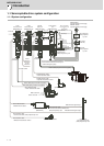
Appendix 1-3 Main circuit cable connection diagram
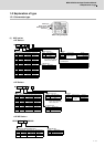
Appendix 1-4 Connector outline dimension drawings
Appendix 1-4-1 Connector for drive unit
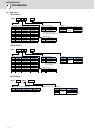
Appendix 1-4-2 Connector for servo and tool
spindle
Appendix 1-4-3 Connector for spindle
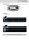
Appendix 2 Cable and Connector Assembly
Appendix 2-1 CM10-SPxxS-x(D6) plug connector
Appendix 2-2 CM10-APxxS-x(D6) angle plug
connector
Appendix 2-3 CM10-SP-CV reinforcing cover for
straight plug
Appendix 2-4 CM10-AP-D-CV reinforcing cover for
angle plug
Appendix 2-5 1747464-1 plug connector
Appendix 2-5-1 Applicable products
Appendix 2-5-2 Applicable cable
Appendix 2-5-3 Related documents
Appendix 2-5-4 Assembly procedure
Appendix 3 Precautions in Installing
Spindle Motor
Appendix 3-1 Precautions in transporting motor