TECHNICAL SPECIFICATIONS
Connectors and Pinouts
350-8697 DGy Model 201 User Guide 133
. . . . .
. . . . . . . . . . . . . . . . . . . . . . . . . . . . .
CONNECTORS AND PINOUTS
This section provides information about the signal and control
connectors used in DGy 201.
• DVI-I Connector
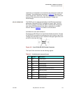
• Composite Video Connector
• Ethernet Connector
• RS-232 Connector
. . . . . . . . .
DVI-I CONNECTOR
The DVI connector is used to interconnect graphics devices. This is a
standard connector based on the work of the Digital Display Working
Group (DDWG).
CONNECTOR TYPE AND PINOUTS
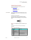
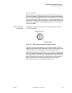
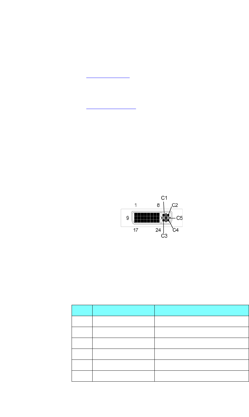
The connector used in the DGy 201 is a 29-pin DVI-I connector,
supporting both analog and digital signals. The DVI-I connector (as
shown below) is used for the standard DGy 201 DVI input and output
signals.
Figure A-16. DVI-I Digital/Analog Connector (viewed from rear of
chassis)
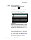
The 29 pin DVI-I connector (Molex #74320) has the following pin
assignments:
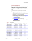
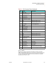
Table A-1. DVI-I Connector Pinout
Pin Signal Description
1 TMDS Data 2-
2 TMDS Data 2+
3 TMDS Data 2/4 shield
4 NC Defined for Dual Link only
5 NC Defined for Dual Link only
6 DDC Clock


