


TECHNICAL SPECIFICATIONS
Connectors and Pinouts
350-8697 DGy Model 201 User Guide 137
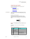
. . . . .
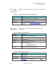
conductors. It is important to use wires from the same pair for each pair
of signals. The standard pairs are shown in
Table A-2. Note that one
wire of the pair has a solid color. The other wire (of the pair) is white with
a stripe of the same color as the other wire (e.g., Orange and
White/Orange).
. . . . . . . . .
RS-232 CONNECTOR
The RS-232 port is configured according to the Electronic Industries
Association Standard RS-232-C published in August 1969. The DGy
201 can be explicitly controlled with ASCII Command Set instructions
sent via the RS-232 serial port from either a computer or an ASCII
terminal. Refer to
Chapter 6, for details on all commands.
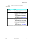
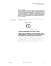
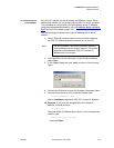
CONNECTOR TYPE AND PINOUTS
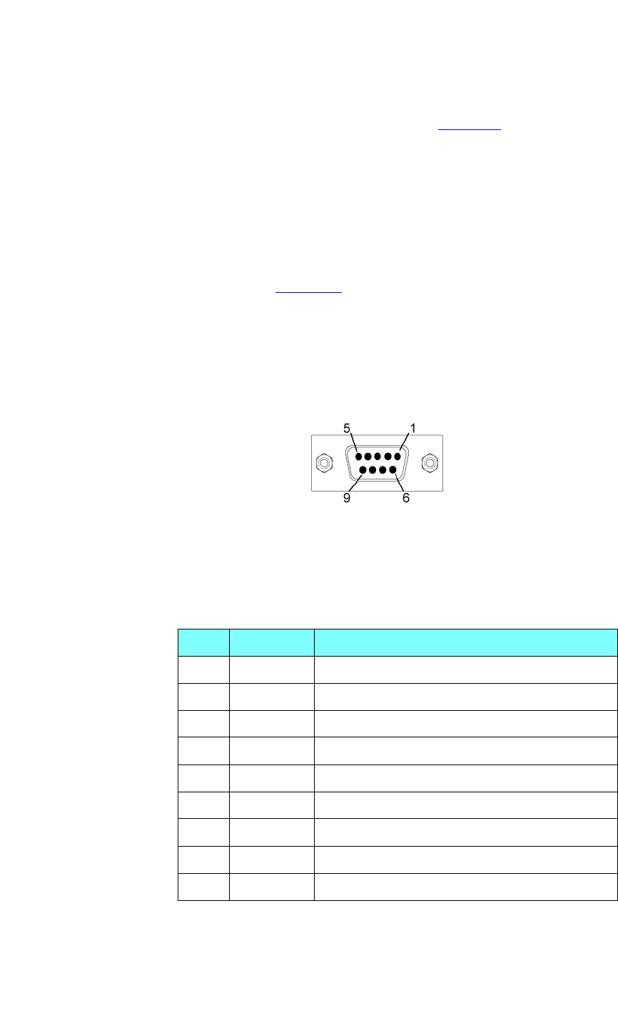
Physically, the RS-232 port is a 9-pin D-Sub female connector. The pins
for the RS-232 connector are numbered from top to bottom, right to left.
Looking at the connector, pin #1 is located in the upper right corner, and
pin #9 is in the lower left corner.
Figure A-3. 9-pin D-Sub RS-232 Female Connector
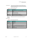
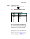
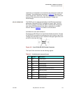
The 9-pin D-Sub connector has the following signals:
Table A-3. RS-232 Serial Connector Pinouts
Pin Circuit Description
1 CD Carrier Detect
2 TD Transmit Data
3 RD Received Data
4 (not connected)
5 AB Signal Ground (common return)
6 DSR Data Set Ready
7 CTS Clear to Send
8 RTS Request to Send
9 (not connected)