


FX Series Programmable Controllers Devices in Detail 4
4-27
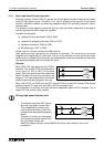
Note: Bi-directional counters are desi
g
ned such that the up count si
g
nal and the down count
si
g
nal never operate at the same time. Therefore it is reall
y
usin
g
onl
y
one phase at one time.
Thus, the
y
can be treated in the same wa
y
as the 1 phase counters when calculatin
g
the
combined frequenc
y
.
Combined frequencies:
• The combined frequenc
y
is the sum of the maximum frequencies of all the si
g
nals
simultaneousl
y
appearin
g
at the inputs of the PLC. The criteria is that in order for the
hi
g
h speed counters to count correctl
y
the
y
must have a combined frequenc
y
of less
than 20 kHz.
Example:
The combined frequenc
y
of 14.2 kHz is lower than the maximum of 20 kHz, so this example is
valid.
A/B Phase counters:
When calculatin
g
a combined frequenc
y
which includes an A/B phase counter, the maximum
countin
g
frequenc
y
should be multiplied b
y
a factor of 4 before addin
g
the maximum
frequencies of the combinin
g
counters.
Example:
The combined frequenc
y
of 11 kHz is lower than the maximum of 20 kHz, so this example is
valid.
2 Phase counters:
• When pulses arrive at the up and down count inputs at the same time, treat this as 2
sin
g
le phase counters when calculatin
g
the combined frequenc
y
.
ClockWise - Counter-ClockWise format encoders:
• When encoders with CW and CCW format inputs are used, the bi-directional counters
can count at a much hi
g
her frequenc
y
than the A/B phase counters, there is also no loss
in resolution.
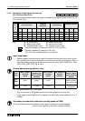
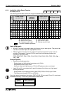
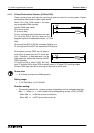
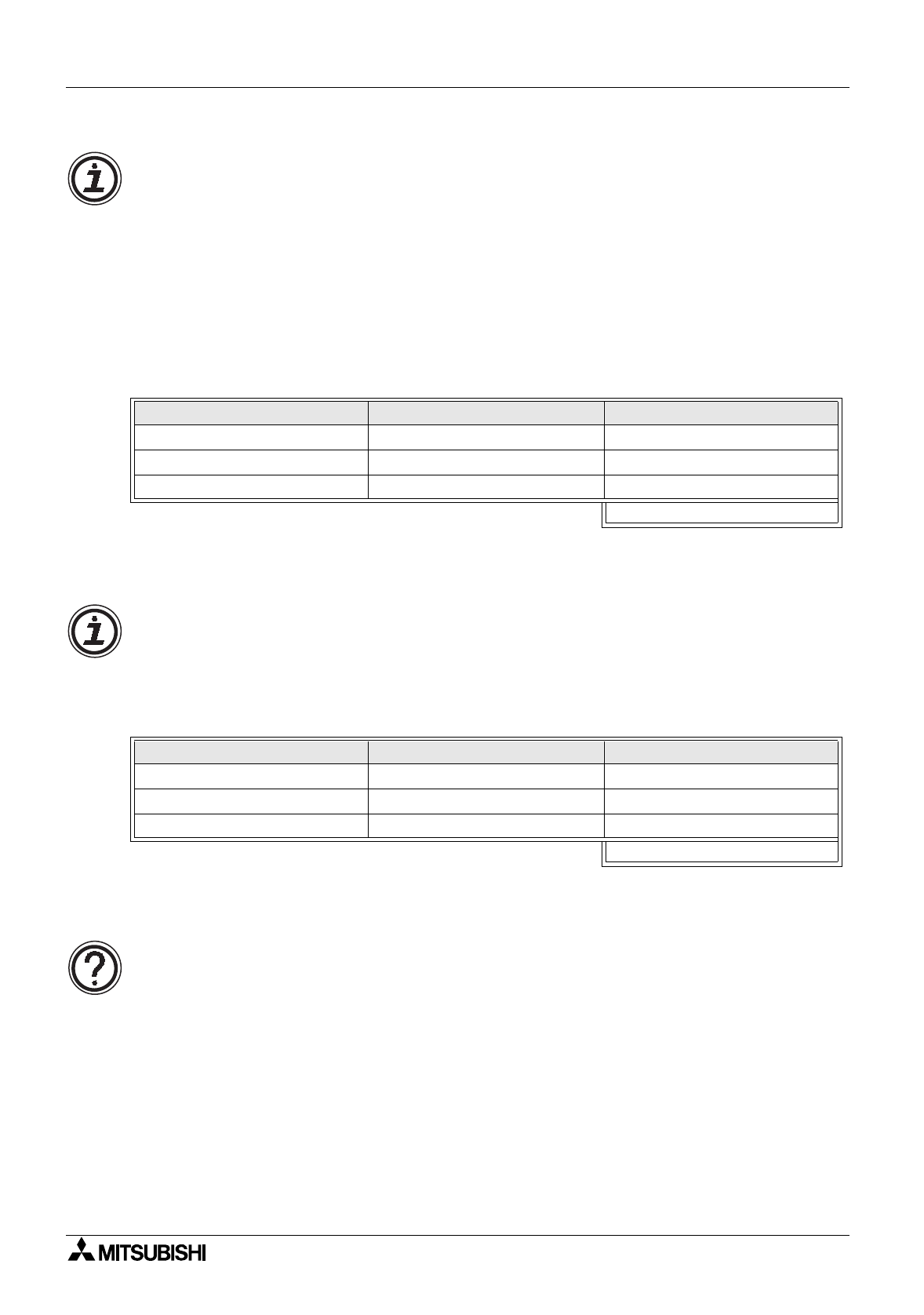
1 Phase counters Corresponding input Maximum signal frequency
C235 X0 4.2 kHz
C237 X2 4 kHz
C240 X3 6 kHz
Combined frequenc
y
14.2kHz
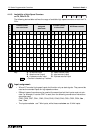
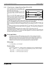
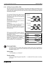
1 Phase counters Corresponding input Maximum signal frequency
1- Phase C237 X2 3 kHz
Bi-directional C246 X0, X1 4 kHz
A/B Phase C255 X3, X4 1 kHz
×
4
Combined frequenc
y
3 + 4 + (1
×
4) = 11kHz