


FX Series Programmable Controllers Devices in Detail 4
4-18
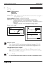
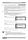
4.9.4 Timers Used in Interrupt and ‘CALL’ Subroutines
If timers T192 to T199 and T246 to T249 are used in a CALL subroutine or an interruption
routine, the timin
g
action is updated at the point when an END instruction is executed. The
output contact is activated when a coil instruction or an END instruction is processed once the
timers current value has reached the preset (maximum duration) value.
Timers other than those specified above cannot function correctl
y
within the specified
circumstances.
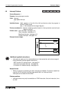
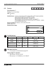
When an interrupt timer (1 msec resolution) is used in an interrupt routine or within a ‘CALL’
subroutine, the output contact is activated when the first coil instruction of that timer is
executed after the timer has reached its preset (maximum duration) value.
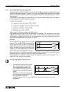
4.9.5 Timer Accuracy
Timer accurac
y
can be affected b
y
the pro
g
ram confi
g
uration. That is to sa
y
, if a timer contact
is used before its associated coil, then the timer accurac
y
is reduced.
The followin
g
formulas
g
ive maximum and minimum errors for certain situations.
However, an avera
g
e expected error would be approximatel
y
;
1.5
×
The pro
g
ram scan time
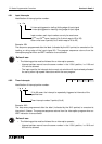
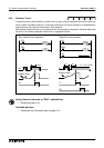
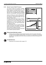
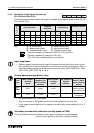
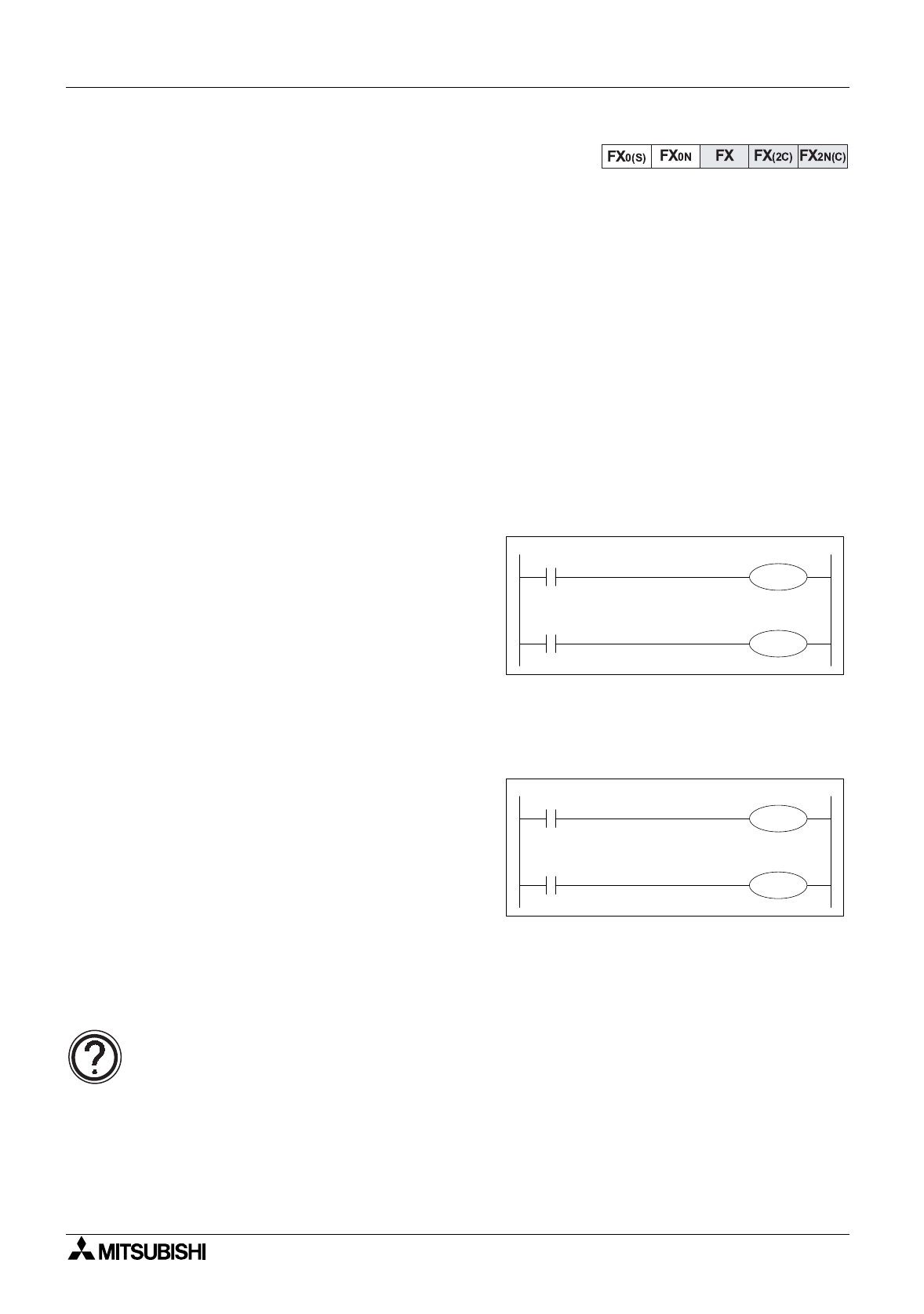
Condition 1:
The timer contact appears after the timer coil.
Maximum timin
g
error:
2
×
Scan time + The input filter time
Minimum timin
g
error:
Input filter time - The timer resolution
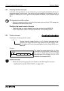
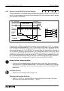
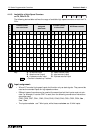
Condition 2:
The timer contact appears before the timer coil.
Maximum timin
g
error:
3
×
Scan time + The input filter time
Minimum timin
g
error:
Input filter time- The timer resolution
Internal timer accuracy:
• The actual accurac
y
of the timin
g
elements within the PLC hardware is;
± 10 pulses per million pulses. This means that if a 100 msec timer is used to time a sin-
g
le da
y
, at the end of that da
y
the timer will be within 0.8 seconds of the true 24 hours or
86,400 seconds. The timer would have processed approximatel
y
864,000; 100 msec
pulses.
X10
T0
T0
Y10
X10
T0
Y10
T0