


FX Series Programmable Controllers Devices in Detail 4
4-28
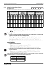
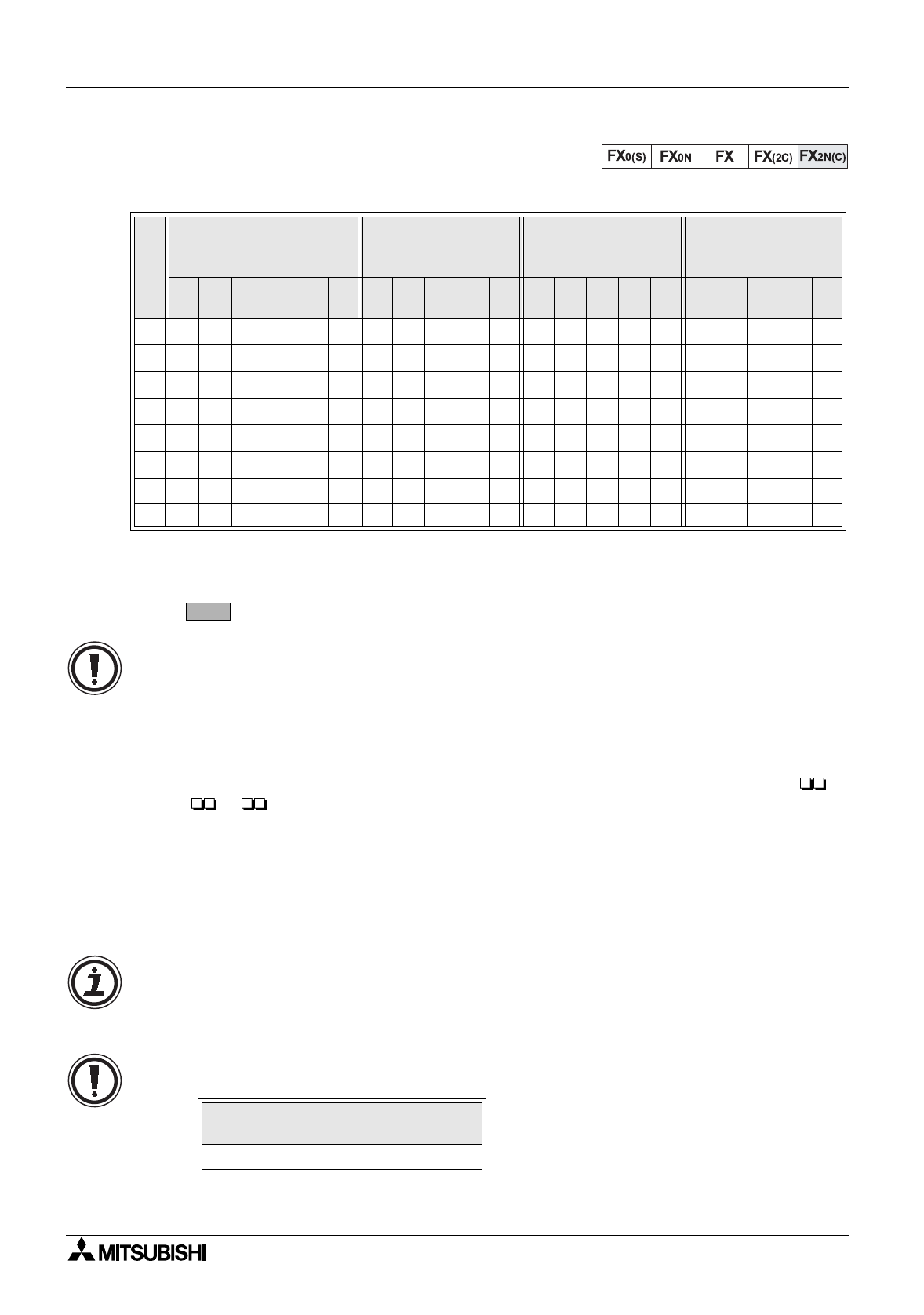
4.11.4 Availability of High Speed Counters
on FX
2N(C)
PLC’s
The followin
g
device table outlines the ran
g
e of available hi
g
h speed counters on FX
2N(C)
.
Ke
y
:
U
- up counter input
D
- down counter input
R
- reset counter (input)
S
- start counter (input)
A
- A phase counter input
B
- B phase counter input
- Counter is backed up/latched
Input assignment:
• X6 and X7 are also hi
g
h speed inputs, but function onl
y
as start si
g
nals. The
y
cannot be
used as the counted inputs for hi
g
h speed counters.
• Different t
y
pes of counters can be used at the same time but their inputs must not
coincide. For example, if counter C247 is used, then the followin
g
counters and
instructions cannot be used;
C235, C236, C237, C241, C242, C244, C245, C246, C249, C251, C252, C254, I0 ,
I1 , I2 .
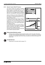
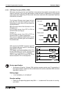
Counter Speeds:
• General countin
g
frequencies:
-Sin
g
le phase and bi-directional counters; up to 10 kHz.
- A/B phase counters; up to 5 kHz.
- Maximum total countin
g
frequenc
y
; 20 kHz (A/B phase counter count twice).
• Inputs X0 and X1 are equipped with special hardware that allows ver
y
hi
g
h speed
countin
g
as follows:
-Sin
g
le phase or bi-directional countin
g
with C235, C236 or C246; up to 60 kHz.
- Two phase countin
g
with C251; up to 30 kHz.
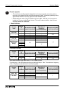
If an
y
hi
g
h speed comparison instructions (FNC’s 53, 54, 55) are used, X0 and X1 must resort
to software countin
g
. In this case, please see the table below:
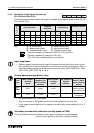
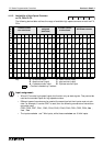
I
N
P
U
T
1 Phase counter
user start/reset
1 Phase counter
assigned
start/reset
2 Phase counter
bi-directional
A/B Phase counter
C235
C236
C237
C238
C239
C240
C241
C242
C243
C244
C245
C246
C247
C248
C249
C250
C251
C252
C253
C254
C255
X0
U/D U/D U/D U U U A A A
X1
U/D R RDDDBBB
X2
U/D U/D U/D R R R R
X3
U/D R S R U U A A
X4
U/D U/D D D B B
X5
U/D R R R R R
X6
SSS
X7
SSS
Function
Number
Max. Combined
Signal Frequency
53 or 54 11 kHz
55 5.5 kHz
C235