


FX Series Programmable Controllers Devices in Detail 4
4-20
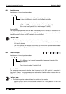
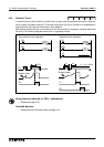
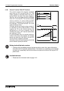
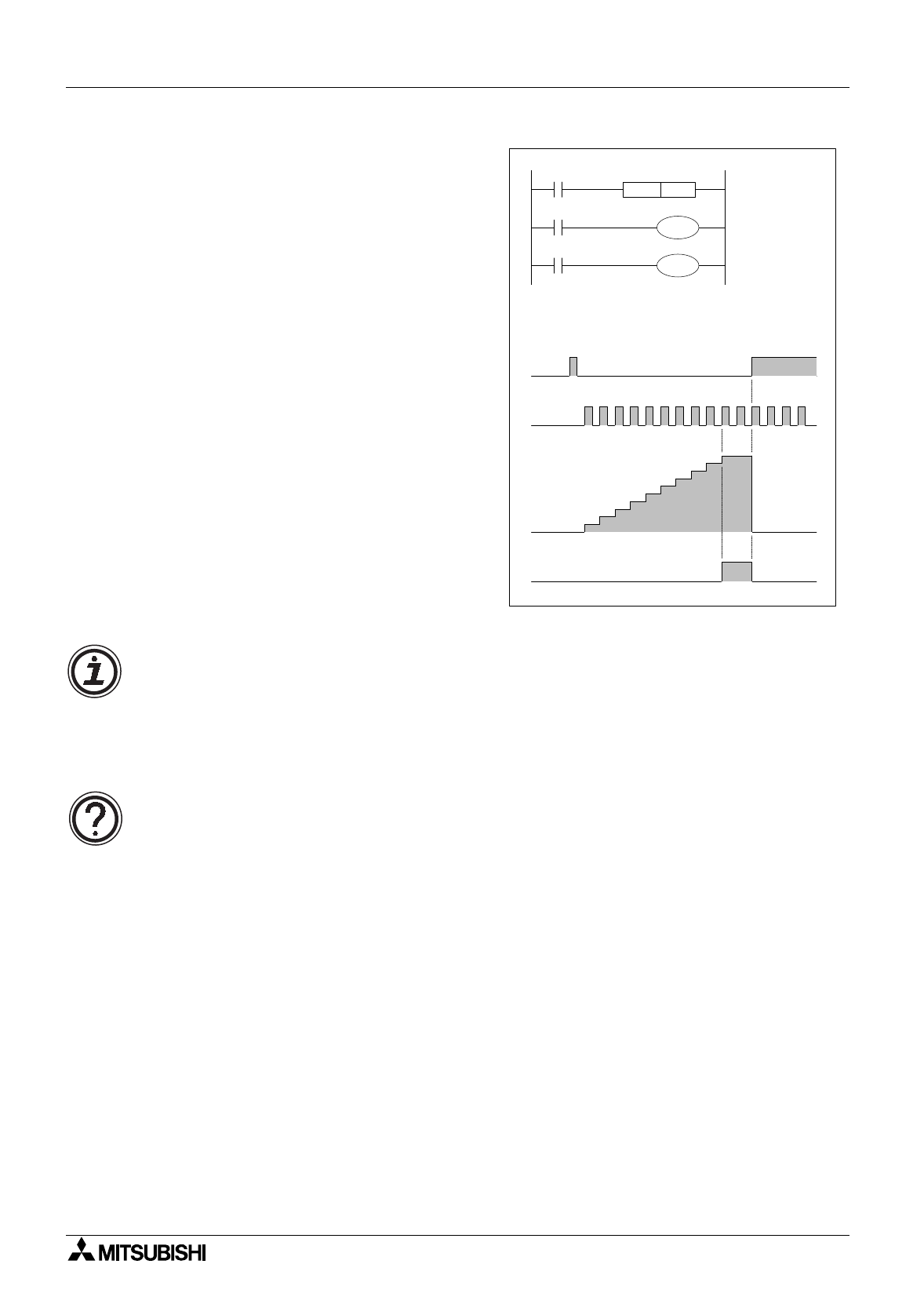
4.10.1 General/ Latched 16bit UP Counters
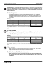
The current value of the counter increases
each time coil C0 is turned ON b
y
X11. The
output contact is activated when the coil is
turned ON for the tenth time (see dia
g
ram).
After this, the counter data remains unchan
g
ed
when X11 is turned ON. The counter current
value is reset to ‘0’ (zero) when the RST
instruction is executed b
y
turnin
g
ON X10 in
the example. The output contact Y0 is also
reset at the same time.
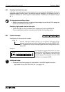
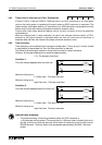
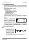
Counters can be set directl
y
usin
g
constant K
or indirectl
y
b
y
usin
g
data stored in a data
re
g
ister (ex. D). In an indirect settin
g
, the
desi
g
nation of D10 for example, which
contains the value “123” has the same effect
as a settin
g
of “K123”.
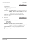
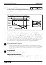
If a value
g
reater than the counter settin
g
is
written to a current value re
g
ister, the counter
counts up when the next input is turned ON.
This is true for all t
y
pes of counters.
Generall
y
, the count input frequenc
y
should be
around several c
y
cles per second.
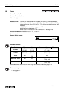
Battery backed/latched counters:
• Counters which are batter
y
backed/ latched are able to retain their status information,
even after the PLC has been powered down. This means on re-powerin
g
up, the latched
counters can immediatel
y
resume from where the
y
were at the time of the ori
g
inal PLC
power down.
Available devices:
• Please see the information table on pa
g
e 4-19.
0
1
2
3
4
5
6
7
8
9
10
X10
X11
Y0
X11
K10
X10
C0RST
C0
C0
Y0