


FX Series Programmable Controllers Basic Program Instructions 2
2-2
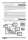
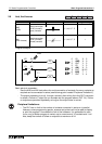
2.3 How to Read Ladder Logic
Ladder lo
g
ic is ver
y
closel
y
associated to basic rela
y
lo
g
ic. There are both contacts and coils
that can be loaded and driven in different confi
g
urations. However, the basic principle remains
the same.
A coil drives direct outputs of the PLC (ex. a Y device) or drives internal timers, counters or
fla
g
s (ex. T, C, M and S devices). Each coil has associated contacts. These contacts are
available in both “normall
y
open” (NO) and “normall
y
closed” (NC) confi
g
urations.
The term “normal(l
y
)” refers to the status of the contacts when the coil is not ener
g
ized. Usin
g
a rela
y
analo
gy
, when the coil is OFF, a NO contact would have no current flow, that is, a load
bein
g
supplied throu
g
h a NO contact would not operate. However, a NC contact would allow
current to flow, hence the connected load would be active.
Activatin
g
the coil reverses the contact status, that is, the current would flow in a NO contact
and a NC contact would inhibit the flow.
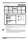
Ph
y
sical inputs to the PLC (X devices) have no pro
g
rammable coil. These devices ma
y
onl
y
be
used in a contact format (NO and NC t
y
pes are available).
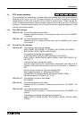
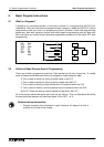
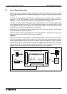
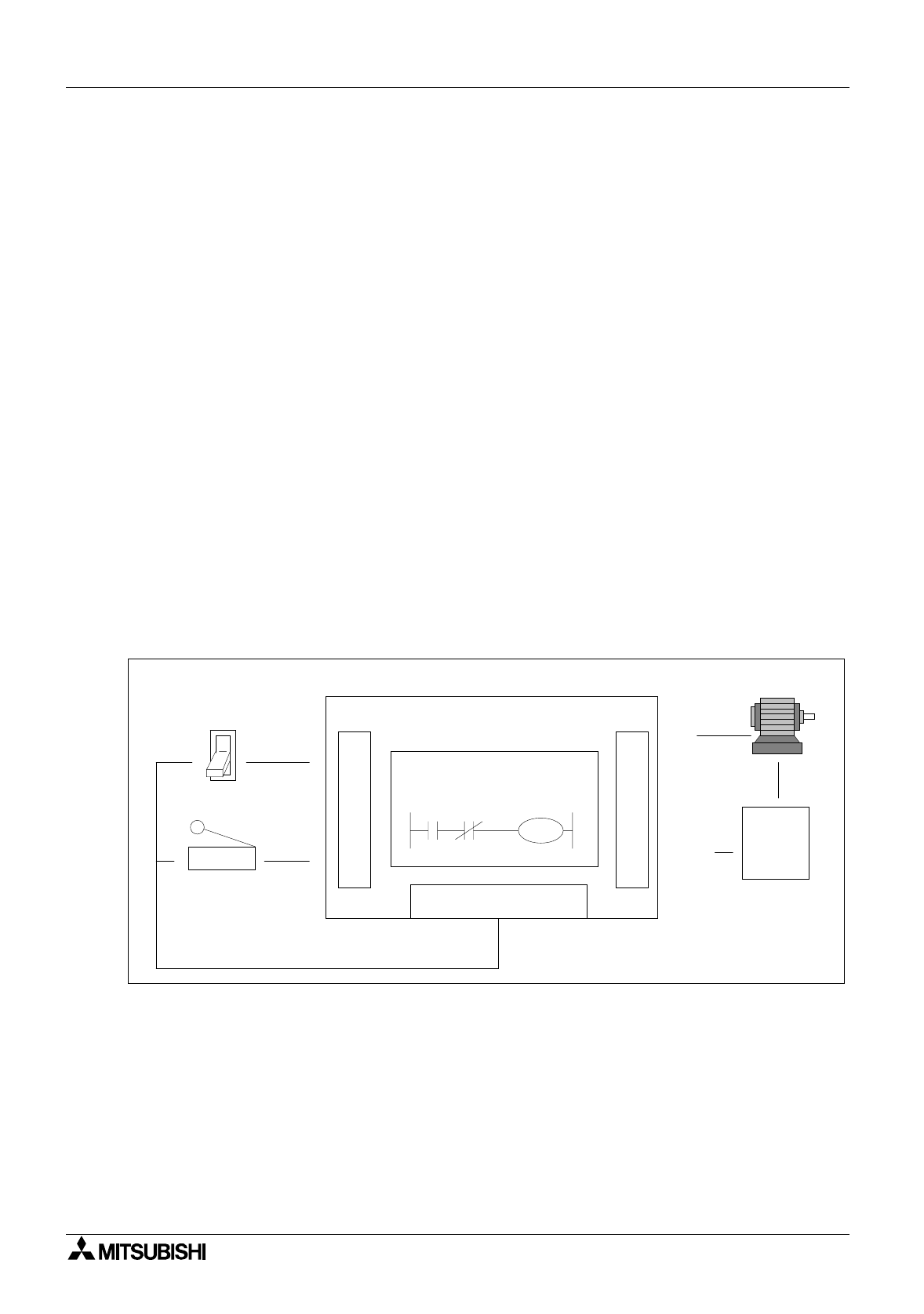
Example:
Because of the close rela
y
association, ladder lo
g
ic pro
g
rams can be read as current flowin
g
from the left vertical line to the ri
g
ht vertical line. This current must pass throu
g
h a series of
contact representations such as X0 and X1 in order to switch the output coil Y0 ON. Therefore,
in the example shown, switchin
g
X0 ON causes the output Y0 to also switch ON. If however,
the limit switch X1 is activates, the output Y0 turns OFF. This is because the connection
between the left and the ri
g
ht vertical lines breaks so there is no current flow.
X0 X1
Y0
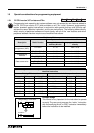
PC Program
I
N
P
U
T
O
U
T
P
U
T
Programmable Controller
DC Power Supply
X0
X1
Y0
AC
Power
Supply
COM
(Y0)
Toggle switch
Limit switch
Motor