


FX Series Programmable Controlers Applied Instructions 5
5-10
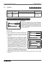
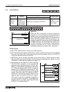
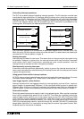
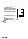
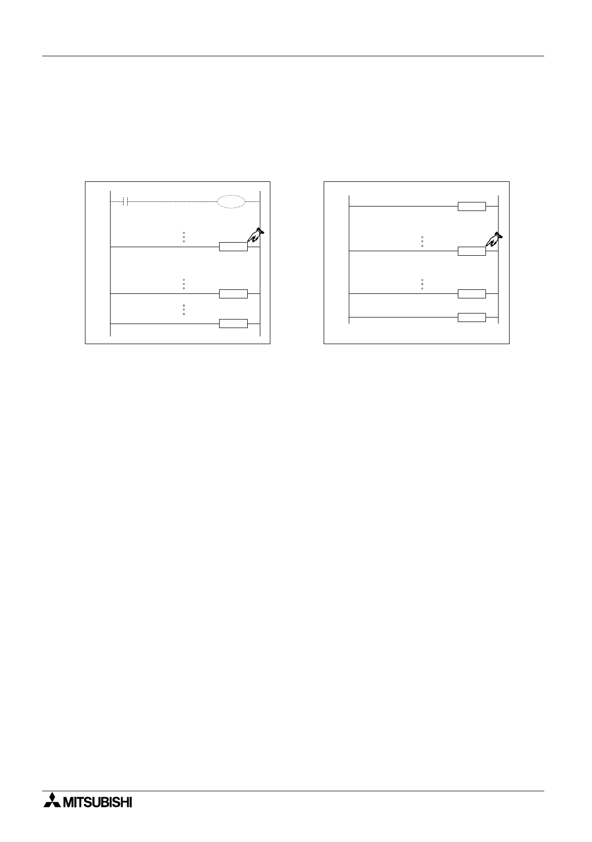
Controlling interrupt operations:
The PLC has a default status of disablin
g
interrupt operation. The EI instruction must be used
to activate the interrupt facilities. All interrupts which ph
y
sicall
y
occur durin
g
the pro
g
ram scan
period from the EI instruction until the FEND or DI instructions will have their associated
interrupt routines run. If these interrupts are tri
gg
ered outside of the enclosed ran
g
e (EI-FEND
or EI-DI, see dia
g
ram below) the
y
will be stored until the EI instruction is processed on the
followin
g
scan. At this point the
interrupt routine will be run.
If an individual interrupt is to be disabled its associated special M coil must be driven ON.
While this coil is ON the interrupt routine will not be activated. For details about the disablin
g
M
coils see the PLC device tables in chapter 8.
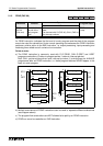
Nesting interrupts:
Interrupts ma
y
be nested for two levels. This means that an interrupt ma
y
be interrupted durin
g
its operation. However, to achieve this, the interrupt routine which ma
y
be further interrupted
must contain the EI and DI instructions; otherwise as under normal operation, when an
interrupt routine is activated all other interrupts are disabled.
Simultaneously occurring interrupts:
If more than one interrupt occurs sequentiall
y
, priorit
y
is
g
iven to the interrupt occurrin
g
first. If
two or more interrupts occur simultaneousl
y
, the interrupt routine with the lower pointer number
is
g
iven the hi
g
her priorit
y
.
Using general timers within interrupt routines:
FX PLC’s have a ran
g
e of special timers which can be used within interrupt routines. For more
information please see pa
g
e 4-18, Timers Used in Interrupt and ‘CALL’ Subroutines.
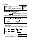
Input trigger signals - pulse duration:
Interrupt routines which are tri
gg
ered directl
y
b
y
interrupt inputs, such as X0 etc., require a
si
g
nal duration of approximatel
y
200
µ
sec, i.e. the input pulse width is equal or
g
reater than
200
µ
sec. When this t
y
pe of interrupt is selected, the hardware input filters are automaticall
y
reset to 50
µ
sec. (under normal operatin
g
circumstances the input filters are set to 10msec.).
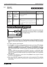
Pulse catch function:
Direct hi
g
h speed inputs can be used to ‘catch’ short pulsed si
g
nals. When a pulse is received
at an input a correspondin
g
special M coil is set ON. This allows the ‘captured’ pulse to be
used to tri
gg
er further actions, even if the ori
g
inal si
g
nal is now OFF. FX0, FX0S and FX0N
units have this function permanentl
y
active for inputs X0 throu
g
h X3 with special M coils
storin
g
the pulse data at M8056 to M8059. FX
(2C)
and FX
2N
units require the EI instruction
(FNC 04) to activate pulse catch for inputs X0 throu
g
h X5, with M8170 to M8175 indicatin
g
the
cau
g
ht pulse. Note that, if an input device is bein
g
used for another hi
g
h speed function, then
the pulse catch for that device is disabled.
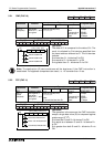
EI
DI
FEND
I301
IRET
Disabled Interrupts
Enabled Interrupts
routine
Interrupt
EI
FEND
IRET
I101
Disabled Interrupts
Enabled Interrupts
routine
Interrupt