


FX Series Programmable Controllers STL Programming 3
3-3
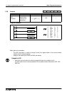
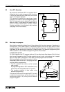
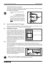
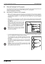
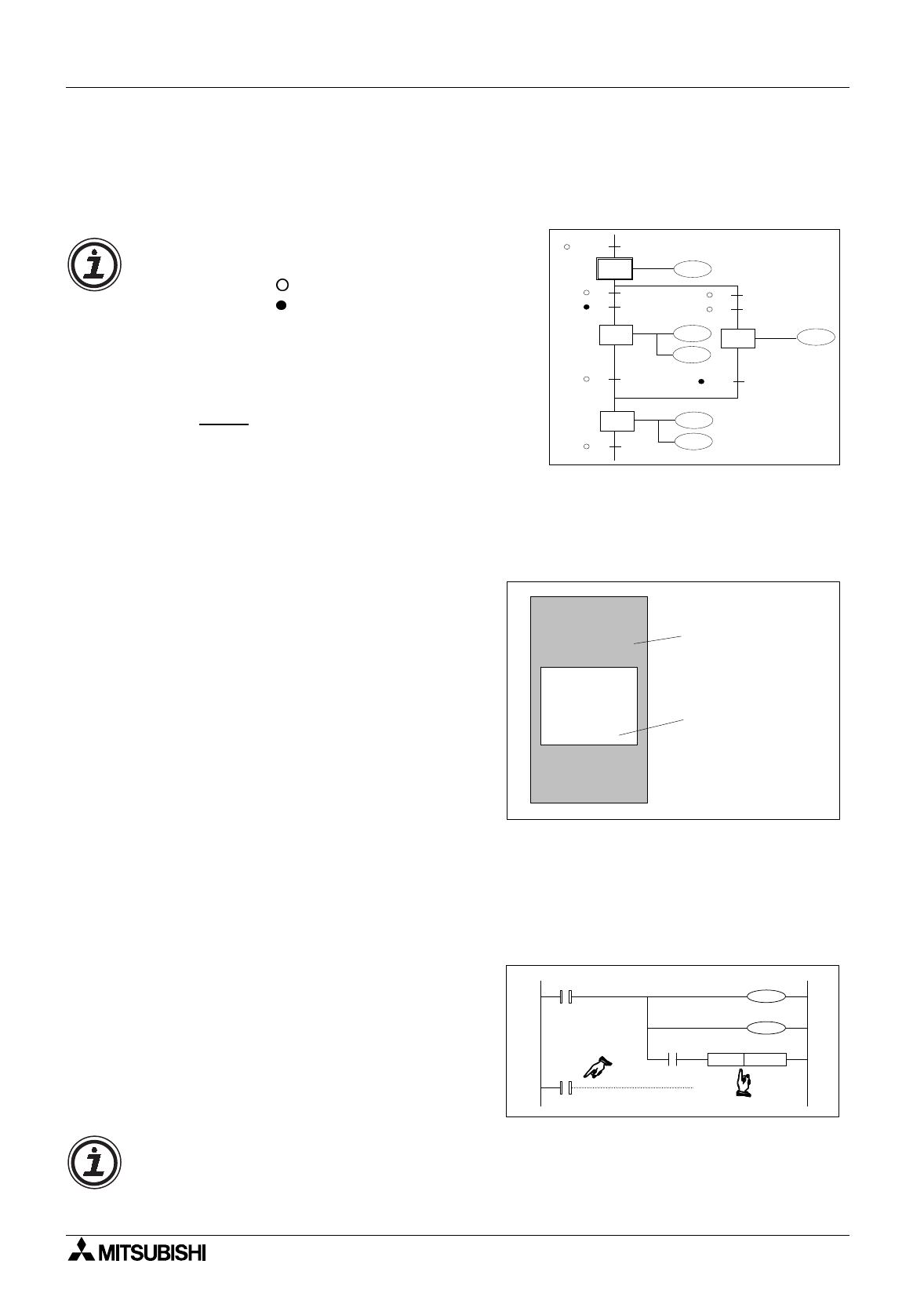
Combined SFC Ladder representation
Sometimes STL pro
g
rams will be written in hard cop
y
as a combination of both flow dia
g
ram
and internal sub-pro
g
ram. (example shown below).
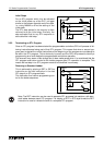
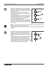
Identification of contact states
3.3 How To Start And End An STL Program
Before an
y
complex pro
g
rammin
g
can be undertaken the basics of how to start and more
importantl
y
how to finish an STL pro
g
ram need to be examined.
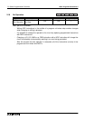
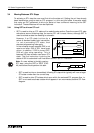
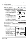
3.3.1 Embedded STL programs
An STL st
y
le pro
g
ram does not have to
entirel
y
replace a standard ladder lo
g
ic
pro
g
ram. In fact it mi
g
ht be ver
y
difficult to do
so. Instead small or even lar
g
e section of STL
pro
g
ram can be entered at an
y
point in a
pro
g
ram. Once the STL task has been
completed the pro
g
ram must
g
o back to
processin
g
standard pro
g
ram instructions until
the next STL pro
g
ram block. Therefore,
identif
y
in
g
the start and end of an STL
pro
g
ram is ver
y
important.
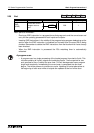
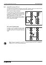
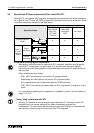
3.3.2 Activating new states
Once an STL step has been selected, how is it used and how is the pro
g
ram ‘driven’?
This is not so difficult, if it is considered that for an STL step to be active its associated state
coil must be ON. Hence, to start an STL sequence all that has to be done is to drive the
relevant state ON.
There are man
y
different methods to drive a
state, for example the initial state coils could
be pulsed, SET or
j
ust included in an OUT
instruction. However, within Mitsubishi’s STL
pro
g
rammin
g
lan
g
ua
g
e an STL coil which is
SET has a different meanin
g
than one that is
included in an OUT instruction.
M8002
X0
X1
S 0
S 26
X0
X1
X15
S 22
S 27
K20
K20
T0
T7
Y22
T0
Y27
T7
Y20
Y26
• Please note the followin
g
convention
is used:
Normall
y
Open contact
Normall
y
Closed contact
Common alternatives are ‘a’ and ‘b’
identifiers for Normall
y
Open,
Normall
y
Closed states or often a line
drawn over the top of the Normall
y
Closed contact name is used, e.
g
.
X000.
LD
OUT
LD
SET
STL
OUT
LDI
OUT
RET
LD
OUT
RST
X000
Y004
X002
S009
S009
Y010
X003
Y006
X005
Y007
M080
Normal Ladder Program
Embedded STL Program
STL
S 22
SET S 27
T0
Y22
T0
K20
STL
S 27
Note: For normal STL operation it is recommended that the states are selected usin
g
the
SET instruction. To activate an STL step its state coil is SET ON.