


FX Series Programmable Controlers Applied Instructions 5
5-96
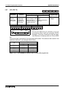
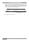
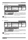
5.9.2 RUN (FNC 81)
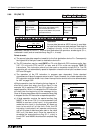
Operation:
This instruction is used with the FX parallel link
adapters. It allows source data to be moved into
the bit transmission area. The actual control of the
parallel link communication is b
y
special M fla
g
s.
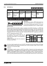
Points to note:
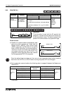
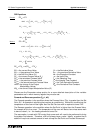
a) Parallel link communications automaticall
y
take
place when both s
y
stems are ‘linked’ and the
Master station (M8070), Slave station fla
g
s
(M8071) have been set ON (there is no need to
have a PRUN instruction for communications).
There can onl
y
be one of each t
y
pe of station as
this s
y
stem connects onl
y
two FX PLC’s. The
pro
g
rams shown opposite should be inserted
into the appropriate FX PLC’s pro
g
rams.
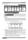
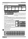
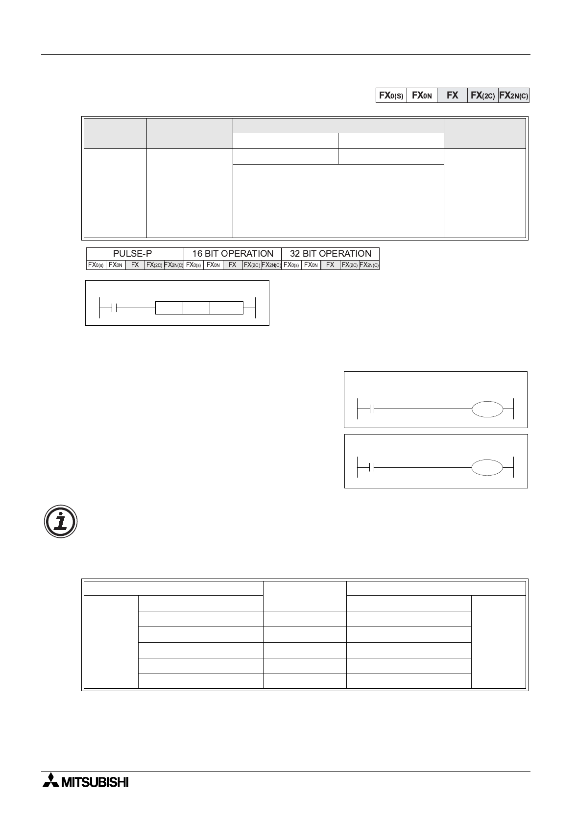
b) Durin
g
automatic communications the followin
g
data is ‘swapped’ between the Master and
Slave PLC’s.
Continued...
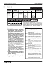
Mnemonic Function
Operands
Program steps
SD
PRUN
FNC 81
(Parallel run)
Used to control
the FX parallel
link adapters:
FX2-40AW/AP
KnX, KnM KnY, KnY PRUN,
PRUNP:
5 steps
DPRUN,
DPRUNP:
9 steps
Note:
n = 1 to 8
For ease and convenience, the head address
bit
should be a multiple of ‘10’, e.
g
. X10, M100,
Y30 etc.
Master station
Communication
direction
Slave Station
M8070 =
ON
Bit Data Bit Data
M8071 =
ON
M800 to M899 (100 points)
→
M800 to M899 (100 points)
M900 to M999 (100 points)
←
M900 to M999 (100 points)
Data words Data words
D490 to D499 (10 points)
→
D490 to D499 (10 points)
D500 to D509 (10 points)
←
D500 to D509 (10 points)
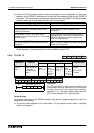
X6
K2X10PRUN
[ D ]
[ S ]
K2M810
M8000
M8070
Master FX PC
Slave FX PC
M8000
M8071
Once the station fla
g
s have been set, the
y
can onl
y
be cleared b
y
either forcibl
y
resettin
g
them when the FX PLC is in STOP mode or turnin
g
the power OFF and ON a
g
ain.