


FX Series Programmable Controlers Applied Instructions 5
5-95
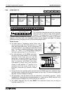
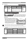
5.9.1 RS (FNC 80)
Operation:
This instruction performs the direct control of
communications over FX and FX
0N
communication
adapters which connect to the left hand port of the
Main Processin
g
Unit, i.e. FX
0N
-232ADP, FX-
232ADP etc.
Points to note:
a) This instruction has man
y
automaticall
y
defined devices. These are listed in the
boxed column to the ri
g
ht of this pa
g
e.
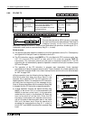
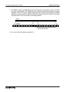
b) The RS instruction has two parts, send
(or transmission) and receive. The first
elements of the RS instruction specif
y
the
transmission data buffer (S) as a head
address, which contains m number of
elements in a sequential stack.
The specification of the receive data area
is contained in the last two parameters of
the RS instruction. The destination (D)
for received messa
g
es has a buffer or
stack len
g
th of n data elements. The size
of the send and receive buffers dictates
how lar
g
e a sin
g
le messa
g
e can be.
Buffer sizes ma
y
be updated at the
followin
g
times:
1) Transmit buffer - before transmission
occurs, i.e. before M8122 is set ON
2) Receive buffer - after a messa
g
e has
been received and before M8123 is
reset.
c) Data cannot be sent while a messa
g
e is
bein
g
received, the transmission will be
dela
y
ed - see M8121.
d) More than one RS instruction can be
pro
g
rammed but onl
y
one ma
y
be active
at an
y
one time.
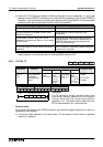
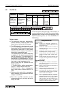
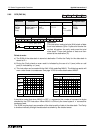
Mnemonic Function
Operands
Program steps
SmDn
RS
FNC 80
(Serial Com-
munications
instruction)
Used to control
serial
communications
from/to the
pro
g
rammable
controller
D
(includin
g
file
re
g
isters)
K, H,
D
m = 1 to
256, FX2N
1 to 4096.
DK, H,
D
m = 1 to
256, FX2N
1 to 4096
RS: 9 steps
X3
K 5
[ S ] [ D ]
D20RS K 5D10
[ m ] [ n ]
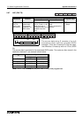
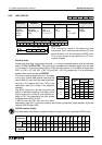
Assigned devices
Data devices:
D8120 -
Contains the configuration parameters for
communication, i.e. Baud rate,Stop bits etc. Full
details over the page
D8122 -
Contains the current count of the number of
remaining bytes to be sent in the currently
transmitting message.
D8123 -
Contains the current count of the number of
received bytes in the ‘incoming’ message.
D8124 -
Contains the ASCII code of the character used
to signify a message header - default is ‘STX’,
02 HEX.
D8125 -
Contains the ASCII code of the character used
to signify a message terminator -default is
‘ETX’, 03 HEX.
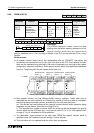
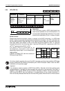
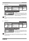
Operational flags:
M8121 -
This flag is ON to indicate a transmission is
being delayed until the current receive
operation is completed.
M8122 -
This flag is used to trigger the transmission of
data when it is set ON.
M8123 -
This flag is used to identify (when ON) that a
complete message has been received.
M8124 -
Carrier detect flag. This flag is for use with FX
and FX2C Main Processing Units. It is typically
useful in modem communications
M8161 -
8 or 16 bit operation mode ON = 8 bit mode
where only the lower 8 bits in each source or
destination device are used, i.e. only one ASCII
character is stored in one data register OFF =
16bit mode where all of the available source/
destination register is used, i.e. two ASCII
characters are stored in each data register.