


FX Series Programmable Controlers Applied Instructions 5
5-55
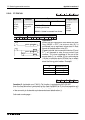
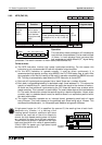
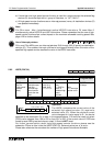
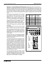
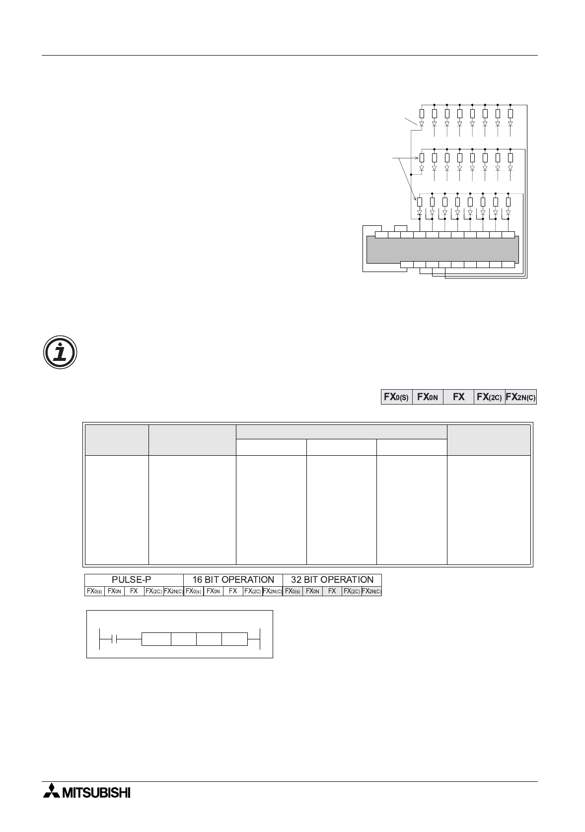
f) Because this instruction uses a series of
multiplexed si
g
nals it requires a certain amount of
‘hard wirin
g
’ to operate. The example wirin
g
dia
g
ram to the ri
g
ht depicts the circuit used if the
previous example instruction was pro
g
rammed. As
a
g
eneral precaution to aid successful operation
diodes should be places after each input device
(see dia
g
ram opposite). These should have a
ratin
g
of 0.1A, 50V.
g
)
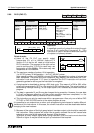
Example Operation
When output Y20 is ON onl
y
those inputs in the
first bank are read. These results are then stored;
in this example, auxiliar
y
coils M30 to M37. The
second step involves Y20
g
oin
g
OFF and Y21
comin
g
ON. This time onl
y
inputs in the second
bank are read. These results are stored in devices
M40 to M47. The last step of this example has Y21
g
oin
g
OFF and Y22 comin
g
ON. This then allows all of the inputs in the third bank to be
read and stored in devices M50 to M57. The processin
g
of this instruction example would
take 20
×
3 = 60msec.
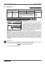
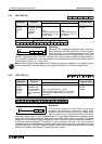
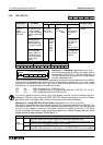
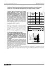
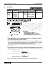
5.6.4 HSCS (FNC 53)
Operation:
The HSCS set, compares the current value of the
selected hi
g
h speed counter (S
2
)a
g
ainst a selected
value (S
1
). When the counters current value
chan
g
es to a value equal to S
1
the device specified
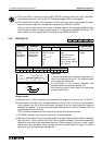
as the destination (D)is set ON.The example above shows that Y10 would be set ON onl
y
when C255’s value stepped from 99-100 OR 101-100. If the counters current value was forced
to equal 100, output Y10 would
NOT
be set ON.
Points to note:
a) It is recommended that the drive input used for the hi
g
h speed counter functions; HSCS,
HSCR, HSCZ is the special auxiliar
y
RUN contact M8000.
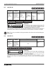
Mnemonic Function
Operands
Program steps
S
1
S
2
n
HSCS
FNC 53
(
Hi
g
h
speed
counter set)
Sets the selected
output when the
specified hi
g
h
speed counter
value equals the
test value
K, H,
KnX, KnY,
KnM, KnS,
T, C, D, V, Z
C
Note:
C = 235 to 254,
or available
hi
g
h speed
counters
Y, M, S
Interrupt point-
ers
I010 to I060
can be set on
FX units from
CPU ver 3.07
and F
X2C
units
DHSCS:
13 steps
X10X11X12X13X14X15X16X1724V 0V S/S
Y22Y23Y24Y25Y26Y27+V Y20Y21
3.
2.
1.
0,1 A
50 V
Diode
Input
devices
Transistor output unit
(source)
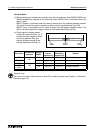
Notice how the resultin
g
matrix-table does not use an
y
of the
P
8 and
P
9 bit devices when
state S or auxiliar
y
M rela
y
s are used as the stora
g
e medium.
M8000
C255 Y10
[ S1 ] [ S2 ]
K100
[ D ]
DHSCS