


FX Series Programmable Controllers Devices in Detail 4
4-41
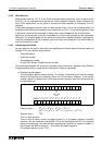
Assigning grouped bit devices:
As alread
y
explained, bit devices can be
g
rouped into 4 bit units. The “n” in KnM0 defines the
number of
g
roups of 4 bits to be combined for data operation. K1 to K4 are allowed for 16bit
data operations but K1 to K8 are valid for 32bit operations.
K2M0, for example identifies 2
g
roups of 4 bits; M0 to M3 and M4 to M7,
g
ivin
g
a total of 8 bit
devices or 1 b
y
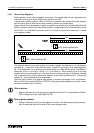
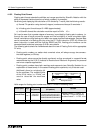
te. The dia
g
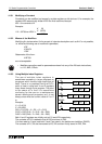
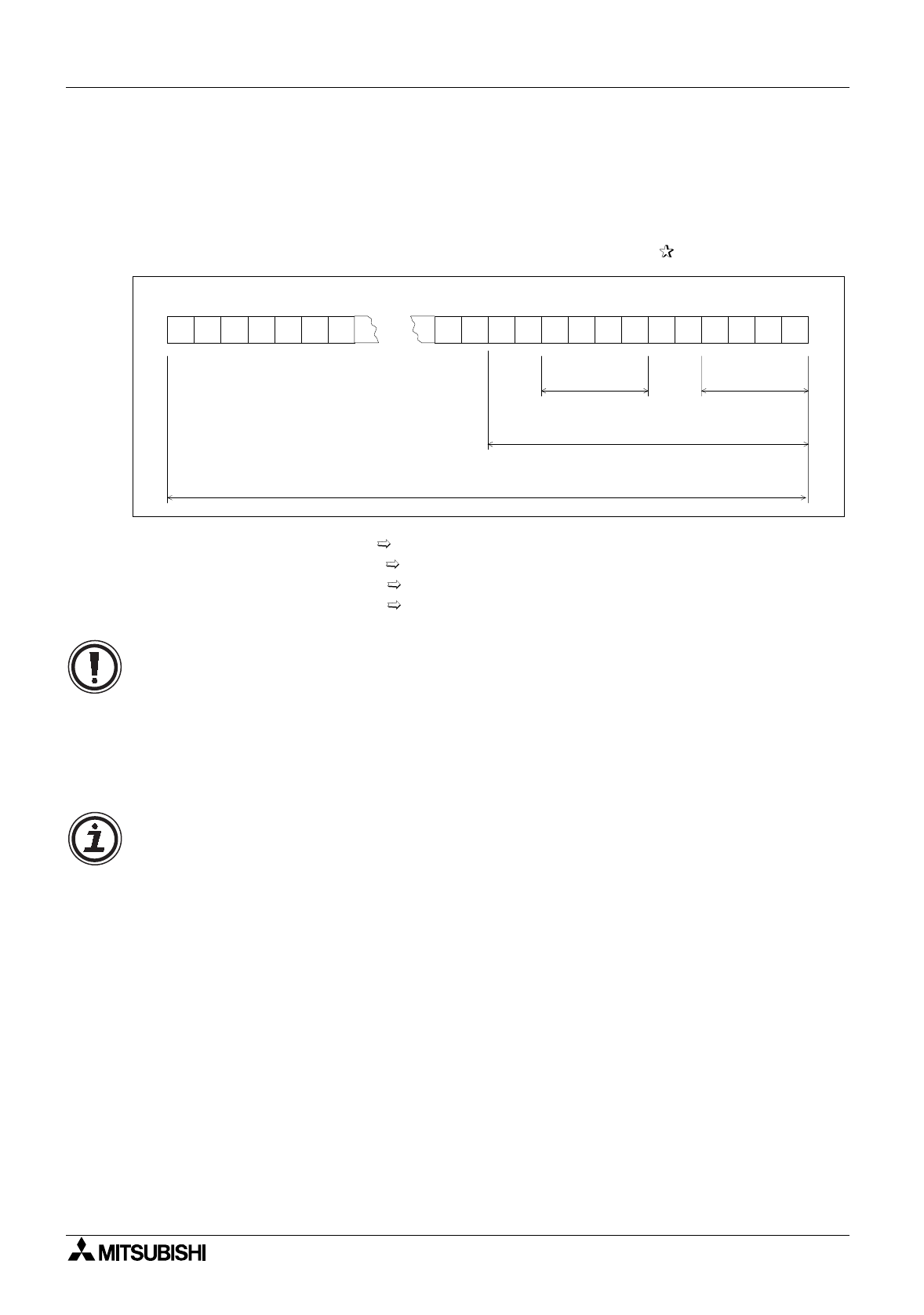
ram below identifies more examples of Kn use.
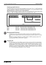
K1X0 : X0 to X3 4 bit devices with a head address of X0
K1X6 : X6 to X11 4 bit devices with a head address of X6
K3X0 : X0 to X13 12 bit devices with a head address of X0
K8X0 : X0 to X37 32 bit devices with a head address of X0
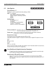
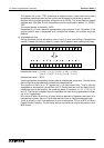
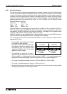
Moving grouped bit devices:
• If a data move involves takin
g
source data and movin
g
it into a destination which is
smaller than the ori
g
inal source, then the overflowin
g
source data is i
g
nored. For exam-
ple;
If K3M20 is moved to K1M0 then onl
y
M20 to M23 or K1M20 is actuall
y
moved. The
remainin
g
data K2M24 or M24 to M31 is i
g
nored.
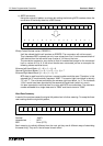
Assigning I/O:
•An
y
value taken from the available ran
g
e of devices can be used for the head address
‘marker’ of a bit device
g
roup. However, it is recommended to use a 0 (zero) in the low-
est di
g
it place of X and Y devices (X0, X10, X20.....etc). For M and S devices, use of a
multiple of “8” is the most device efficient. However, because the use of such numbers
ma
y
lead to confusion in assi
g
nin
g
device numbers, it recommended to use a multiple of
“10”. This will allow
g
ood correlation to X and Y devices.
1 011 010010110010 00 0 1 0
X0X1X2X3X4X5X6X7X10X11X12X13X14X15X16X31X32X33X34X35X36 X30X37
K1X0K1X6
K3X0
K8X0