


FX Series Programmable Controlers Applied Instructions 5
5-76
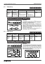
d) When the ‘zero point’ input (D+2) is received the contents of device S+0is reset to ‘0’ (zero).
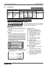
Before startin
g
an
y
new operation it is advisable to ensure the rotar
y
table is initialized b
y
movin
g
the ‘zero point’ drive do
g
or marker around to the ‘zero point’ sensor. This could be
considered as a calibration technique. The re-calibration of the rotar
y
table should be
carried out periodicall
y
to ensure a consistent/accurate operation.
e) Devices D+3 to D+7 are automaticall
y
set b
y
the ROTC instruction durin
g
its operation.
These are used as fla
g
s to indicate the operation which should be carried out next.
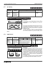
f) All positions are entered in the form of the required encoder pulses. This can be seen in the
followin
g
example:
- Example:
A rotar
y
table has an encoder which outputs 400 (m1) pulses per revolution. There are 8
stations (0 to 7) on the rotar
y
table. This means that when the rotar
y
table moves from one
station to its immediatel
y
followin
g
station, 50 encoder pulses are counted. The ‘zero
position’ is station ‘0’ (zero). To move the item located at station 7 to station 3 the followin
g
values must be written to the ROTC
instruction:
S+1=3
×
50 = 150 (station 3’s position in encoder pulses from the zero point)
S+2=7
×
50 = 350 (station 7’s position in encoder pulses from the zero point)
m1= 400 (total number of encoder pulses per rev)
The rotar
y
table is required approach the destination station at a slow speed startin
g
from
1.5 stations before the destination. Therefor;
m2= 1.5
×
50 = 75 slow speed distance either side of the destination station (in
encoder
pulses)