


FX Series Programmable Controllers Basic Program Instructions 2
2-19
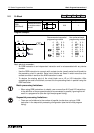
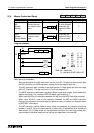
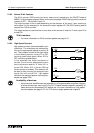
2.16.2 Normal 32 bit Counters
The 32 bit counter C200 counts (up-count, down-count) accordin
g
to the ON/OFF state of
M8200. In the example pro
g
ram shown on the previous pa
g
e C200 is bein
g
used to count the
number of OFF ~ ON c
y
cles of input X4.
The output contact is set or reset dependin
g
on the direction of the count, upon reachin
g
a
value equal (in this example) to the contents of data re
g
isters D1,D0 (32 bit settin
g
data is
required for a 32 bit counter).
The output contact is reset and the current value of the counter is reset to ‘0’ when input X3 is
turned ON.
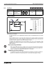
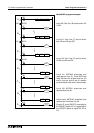
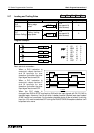
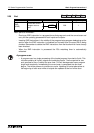
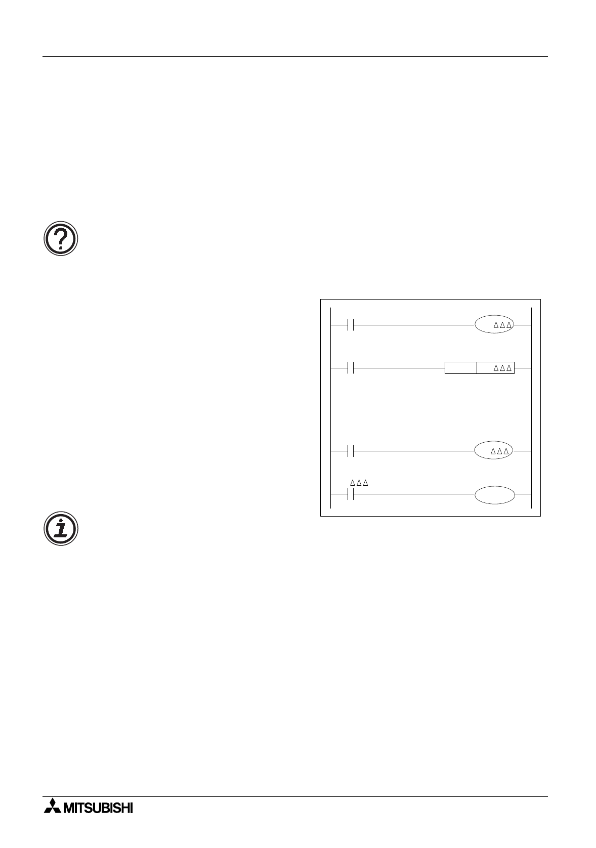
2.16.3 High Speed Counters
Hi
g
h speed counters have selectable count
directions. The directions are selected b
y
drivin
g
the appropriate special auxiliar
y
M
coil. The example shown to the ri
g
ht works
in the followin
g
manner; when X10 is ON,
countin
g
down takes place. When X10 is
OFF countin
g
up takes place.
In the example the output contacts of
counter C
∆∆∆
and its associated current
count values are reset to “0” when X11 is
turned ON. When X12 is turned ON the
driven counter is enabled. This means it will
be able to start countin
g
its assi
g
ned input
si
g
nal (this will not be X12 - hi
g
h speed
counters are assi
g
ned special input si
g
nals,
please see pa
g
e 4-22).
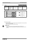
32 bit counters:
• For more information on 32 bit counters please see pa
g
e 4-21.
X10
X11
RST
X12
K/D
C
M8
C
C
Y2
Availability of devices:
• Not all devices identified here are available on all pro
g
rammable controllers. Ran
g
es
of active devices ma
y
var
y
from PLC to PLC. Please check the specific availabilit
y
of
these devices on the selected PLC before use. For more information on hi
g
h speed
counters please see pa
g
e 4-22. For PLC device ran
g
es please see chapter 8.