


FX Series Programmable Controllers Points Of Technique 10
10-15
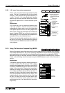
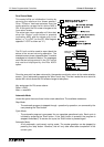
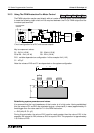
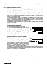
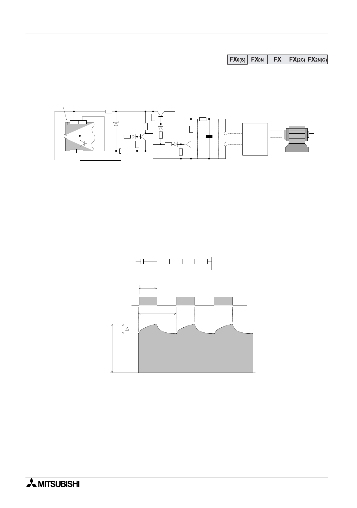
10.13 Using The PWM Instruction For Motor Control
The PWM instruction ma
y
be used directl
y
with an inverter to drive a motor. If this confi
g
uration
is used the followin
g
ripple circuit will be required between the PLC’s PWM output and the
inverters input terminals.
Ke
y
to component values:
R1 - 510
Ω
(1/2 W) R2 - 3.3k
Ω
(1/2 W)
R3 to R8 - 1k
Ω
(1/4 W) R9 - 22
Ω
(1/4 W)
R10 - variable dependent on confi
g
uration. In this example 1k
Ω
(1 W)
C1 - 470
µ
F
Note: the values of R10 and C1 are dependent on the s
y
stem confi
g
uration.
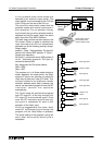
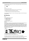
Establishing system parameters and values
It is assumed that the input impedance of the inverter is of a hi
g
h order. Havin
g
established
this, the values of C1 and R10 are calculated to
g
ive
τ
a time result (in msec) approximatel
y
10
times bi
gg
er than the value used for T
0
in the PWM instruction:
τ
= R10 (k
Ω
)
Å
L C1 (
µ
F)
Durin
g
this calculation the value of R10 must be vastl
y
g
reater than the value of R9. In the
example, R9 is equal to 22
Ω
, where as R10 is equal to 1k
Ω
. This proportion is approximatel
y
1:50 in favor of R10.
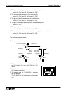
Y0+V0
24V 0V
+
E
e
R1
R2
R3 R7
R10
R
4
R
5
R
6
R
9
R
8
Inverter
C1
5V
12V
Programmable
controller
Motor
Circuit confi
g
uration for a PLC with source outputs
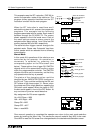
e
e
m
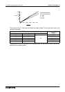
Y000
t
T
0
PWM D10 K50 Y000
X10
tT0