


FX Series Programmable Controllers Points Of Technique 10
10-23
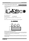
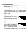
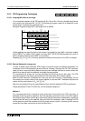
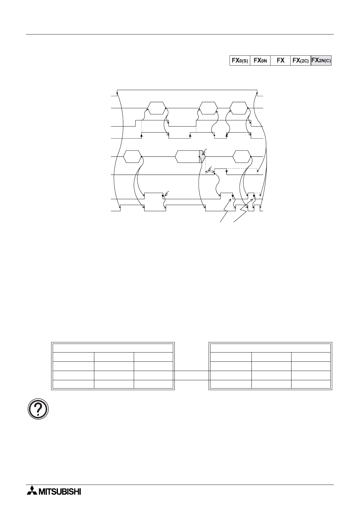
4) Interlink Mode D8120 (b12, b11, b10) = (0, 1, 0)
10.14.4 8 bit or 16 bit communications.
This is to
gg
led usin
g
the Auxiliar
y
rela
y
M8161. When this rela
y
is OFF 16 bit communications
takes place. This actuall
y
means that both b
y
tes of a 16 bit data device are used in both the
transmission and the receipt of messa
g
es. If the M8161 device is activated then 8 bit mode is
selected. In this mode onl
y
the lower 8 bits (or b
y
te) is used to perform the transmission-
receivin
g
actions. The to
gg
lin
g
of the M8161 device should onl
y
occur when the RS instruction
is not active, i.e. it is OFF.
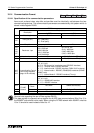
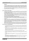
When a buffer area is specified in the RS instruction it is important to check whether 8 or 16bit
mode has been selected, i.e. a buffer area specified as D50 K3 would produce the followin
g
results.......
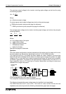
General note re
g
ardin
g
hardware:
Information re
g
ardin
g
pin outs of the respective ADP special function blocks can be found
alon
g
with wirin
g
details in the appropriate hardware manuals.
16 bit mode - M8161 = OFF 8 bit mode - M8161 = ON
Data re
g
ister Hi
g
h b
y
te Low b
y
te Data re
g
ister Hi
g
h b
y
te Low b
y
te
D50 X F D50 F
D51 0 D51 X
D52 0
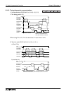
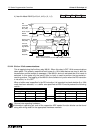
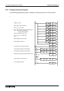
Reset using a program.
When it is not trurned off,the
next data cannot be received.
Data 2
RS
instruction
Send data
SD (TXD)
OFF ON
Data 4
OFFONSend request
M8122
Receive
completion
M8123
Data 4
Data 1
Data 3
Receive data
RD (RXD)
OFF ON
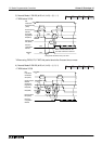
*1 *1 *1
Data 3
*3
Time-out
evaluation time
D8129
×
10ms
OFF ON ON
ON
Reset usin
g
a pro
g
ram.
When it is not turned off, the next data cannot be received.
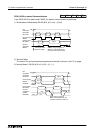
OFFON
DR(DSR)
Time-out
evaluation
fla
g
M8129
Up to 30 characfers
can be received *2
ER(DTR)