


FX Series Programmable Controllers Points Of Technique 10
10-5
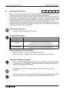
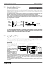
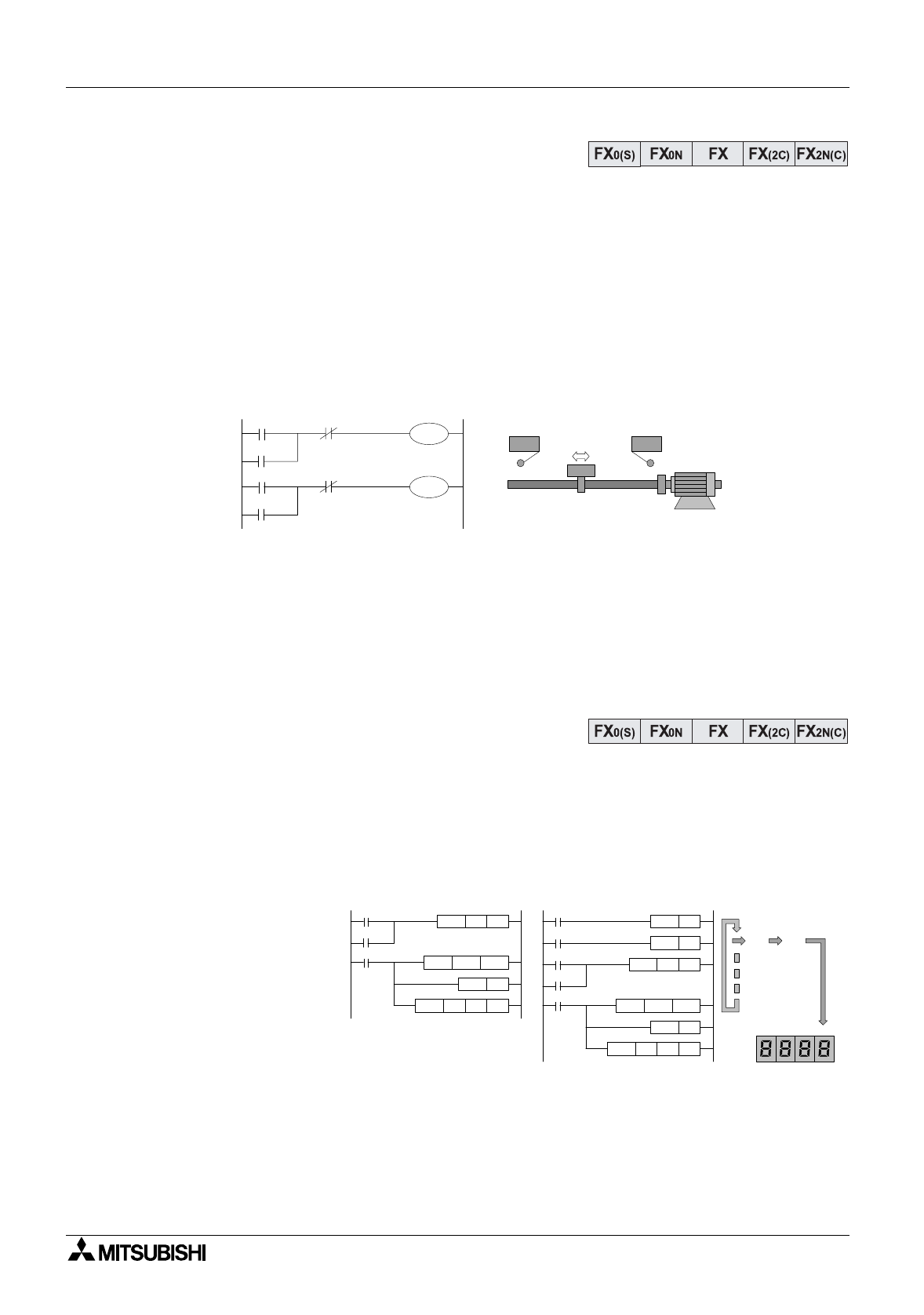
10.6 Using Battery Backed Devices
For Maximum Advantage
Batter
y
backed devices retain their status durin
g
a PLC power down. These devices can be
used for maximum advanta
g
e b
y
allowin
g
the PLC to continue from its last operation status
j
ust before the power failure.
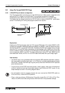
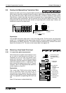
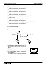
For example: A table traverse s
y
stem is operatin
g
, movin
g
alternativel
y
between two limit
switches. If a PLC power failure occurs durin
g
the traversin
g
the machine will stop.
Ideall
y
, once the PLC re
g
ains its power the s
y
stem should continue from where it left off, i.e. if
the movement direction was to the left before the power down, it should continue to the left
after the restoration of the power.
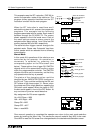
Explanation:
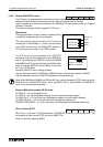
The status of the latched devices (in this example FX M coils M600 and M601) is retained
durin
g
the power down. Once the power is restored the batter
y
backed M coils latch
themselves in a
g
ain, i.e. the load M600 is used to drive M600.
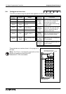
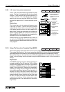
10.7 Indexing Through Multiple
Display Data Values
Man
y
users unwaril
y
fall in to the trap of onl
y
usin
g
a sin
g
le seven se
g
ment displa
y
to displa
y
onl
y
a sin
g
le data value. This ver
y
simple combination of applied instructions shows how a
user can 'pa
g
e' throu
g
h multiple data values displa
y
in
g
each in turn.
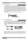
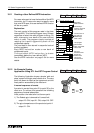
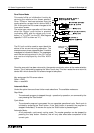
Explanation:
The contents of 10
counters are displa
y
ed in
a sequential, 'pa
g
ed'
operation.
The pa
g
in
g
action occurs
ever
y
time the input X11 is
received.
What actuall
y
hap-pens is
that the index re
g
ister Z is
continuall
y
incremented
until it equals 9. When this happens the comparison instruction drives M1 ON which in turn
resets the current value of Z to 0 (zero). Hence, a loop effect is created with Z var
y
in
g
between
fixed values of 0 and 9 (10 values). The Z value is used to select the next counter to be
displa
y
ed on the seven se
g
ment displa
y
.
This is because the Z index modifier is used to offset the counter bein
g
read b
y
the BCD output
instruction.
X0
X1
M600
M601
X0
M601
X1
M600
Limit switch X0 Limit switch X1
Reciprocating
table
Motor driven
indirectly by
M600 and M601
Ri
g
ht
traverse
Left
traverse
X10
X11
M 1
MOVP
K0
Z
CMPP K9 Z
BCDP
M0
Z
C 0 Z K4 Y0
INC P
M10
M11
M 1
MOV K0 Z
CMP K9 Z
BCD
M0
Z
C 0 Z K4 Y0
INC
X11
PLS M11
X10
PLS M10
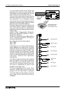
C 0
C 1
C 2
C 3
C 4
C 5
C 6
C 7
C 8
C 9
Z=0
Z=1
Z=2
Z=3
Z=4
Z=5
Z=6
Z=7
Z=8
Z=9
K4 Y0
FX version of program
FX
0
/FX
0N
version of
program
Operation