


FX Series Programmable Controllers Points Of Technique 10
10-12
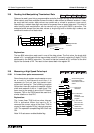
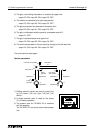
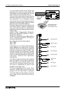
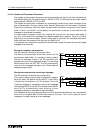
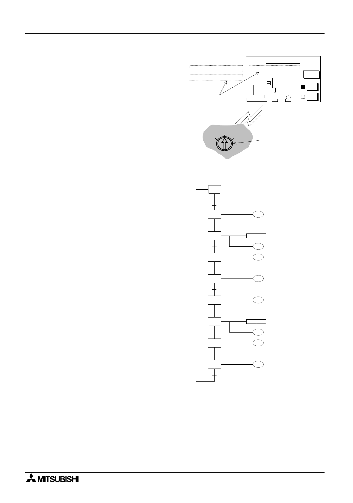
In this example these three modes are
selected b
y
an external rotar
y
switch. The
rotar
y
switch is not connected to the PLC but
to the I/O bus on the rear of the DU unit.
The use of the rotar
y
switch means that the
selected modes are mutuall
y
exclusive in
their operation. For an operator friendl
y
environment the currentl
y
selected mode is
displa
y
ed on the DU screen (a
g
ain this could
be b
y
use of the DUs ASCII function).
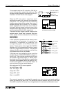
The start/ stop controls are touch ke
y
s on the
DU screen. When a mode is selected the
input received at the DU unit momentaril
y
activates one of the followin
g
auxiliar
y
rela
y
s:
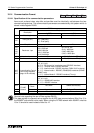
Rotar
y
switch:
position 1 'Step' - Step operation: DU input I0,
controls bit device M32 position 2 'C
y
cle' -
Sin
g
le c
y
cle operation:
DU input I1, controls bit device M33 position 3
'Auto' - Automatic operation: DU input I2,
controls bit device M34
Ke
y
assi
g
nment for DU screen above:
Start = M36
Stop = M37
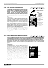
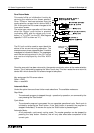
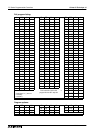
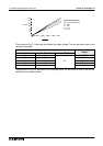
The pro
g
ram run in all three mode choices is
shown opposite. As noted earlier, the 'Step'
mode will require an operator to press the
'Start' ke
y
to start each new STL block. This
could be viewed as an additional transfer
condition between each state. However, the
user is not required to pro
g
ram this as the IST
instruction controls this operation
automaticall
y
.
The 'C
y
cle' mode will process the pro
g
ram
from STL step S2, all the wa
y
throu
g
h until
STL step S2 is encountered a
g
ain. Once
more the IST instruction ensures that onl
y
one c
y
cle is completed for each initial
activation of the 'Start' input.
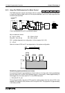
Finall
y
as su
gg
ested b
y
the name, 'Auto'
mode will continuousl
y
c
y
cle throu
g
h the
pro
g
ram until the 'Stop' button is pressed.
The actual haltin
g
of the pro
g
ram c
y
clin
g
will
occur when the currentl
y
active c
y
cle is
completed.
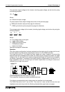
Automatic Mode
AB
Menu
Start
Stop
Automatic Operation
Single Cycle Operation
Stepped Operation
AUTOSTEP
CYCLE
Current
Operation
messages
Rotary switch input to
DU through I/O bus
(used to select mode).
Y0
X1
T0
Y2
X2
S 2
SET Y1
M8041
M8044
T0
K10
Y3
S 20
S 21
S 22
S 23
T1
RST Y1
T1
K10
X3
Y0
S 24
X1
S 25
Y2
S 26
X2
Y4
X4
S 27
Move grip down
Clamp is active
Move grip up
Move grip right
Move grip down
Clamp is not
active
Move grip up
Move grip left