


FX Series Programmable Controllers Points Of Technique 10
10-16
The maximum output volta
g
e (to the inverter) includin
g
ripple volta
g
e, can be found b
y
usin
g
the followin
g
equation:
Where:
e
m
= Maximum output volta
g
e
E
= pulse (square wave) output volta
g
e (see circuit on the previous pa
g
e)
t
= PWM pulse duration (see previous pa
g
e for reference)
T
0
= PWM c
y
cle time for pulse (see previous pa
g
e for reference)
The avera
g
e output volta
g
e (to the inverter) includin
g
ripple volta
g
e, can be found b
y
usin
g
the
followin
g
equation:
Where:
∆
e
= the volta
g
e value of the ripple
e
= ripple output volta
g
e
T
0
= PWM c
y
cle time for pulse
t
= PWM pulse duration
τ
= ripple circuit dela
y
See previous pa
g
e for references.
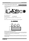
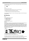
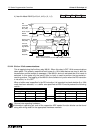
Operation
Once the s
y
stem confi
g
uration has been selected and the ripple circuit has been built to suit,
the motor speed ma
y
be varied b
y
ad
j
ustin
g
the value of 't' in the PWM instruction.
The lar
g
er the value of 't' the faster the motor speed will rotate. However, this should be
balanced with the knowled
g
e that the faster the output si
g
nal chan
g
es the
g
reater the ripple
volta
g
e will be. On the other hand a slowl
y
chan
g
in
g
output si
g
nal will have a more controlled,
y
et smaller ripple effect. The speed of the si
g
nal chan
g
e is determined b
y
the size of C1. A
lar
g
e capacitive value for C1 would
g
ive a smaller ripple effect as char
g
e is stored and
released over a lon
g
er time period.
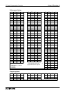
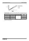
The followin
g
characteristics were noticed when the identified circuit was tested
The PWM instruction had T
0
set to K50. The value for t was varied and also the load
impedance was varied to provide the followin
g
characteristics
g
raph (see over pa
g
e).
e
m
≈
E
t
T
0
T
0
- t
τ
∆
e
e
≈
T
0
τ
≤
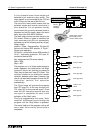
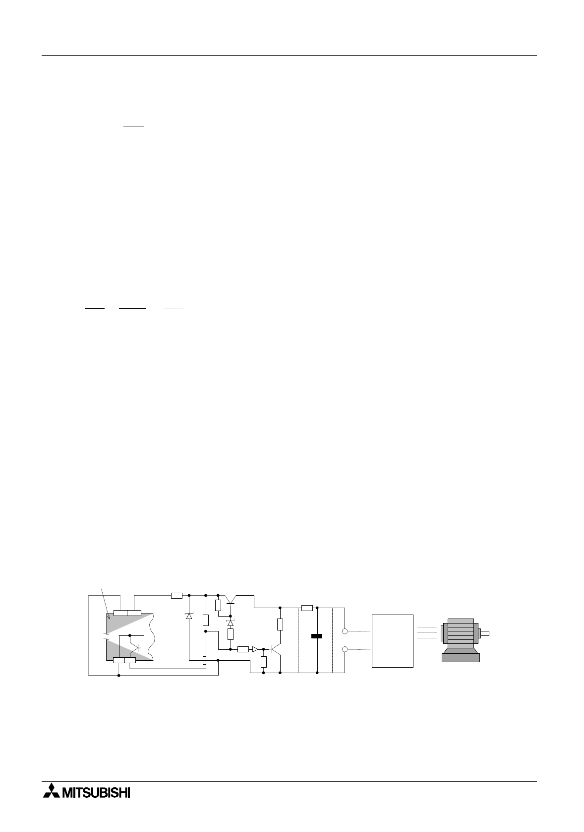
Y0
COM1
COM
24+
+
E
e
R1
R10
R7
R
4
R
5
R
6
R
9
R
8
Motor
Inverter
C1
5V
12V
Programmable
controller
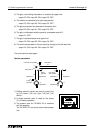
Circuit confi
g
uration for a PLC with sink outputs.
The component values are the same as stated previousl
y