


FX Series Programmable Controlers Applied Instructions 5
5-67
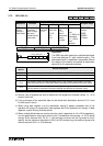
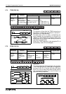
5.7.1 IST (FNC 60)
Operation:
This instruction automaticall
y
sets up a multi-mode
STL operatin
g
s
y
stem. This consists of variations
of ‘manual’ and ‘automatic’ operation modes.
Points to note:
a) The IST instruction automaticall
y
assi
g
ns
and uses man
y
bit fla
g
s and word devices;
these are listed in the boxed column on the
ri
g
ht of this pa
g
e.
b) The IST instruction ma
y
onl
y
be used
ONCE
.
It should be pro
g
rammed close to the
be
g
innin
g
of the pro
g
ram, before the
controlled STL circuits.
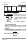
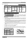
c) The required operation mode is selected b
y
drivin
g
the devices associated with
operands
S+0throu
g
h to S+4(5 inputs). None of the
devices within this ran
g
e should be ON at
the same time. It is recommended that these
‘inputs’ are selected throu
g
h use of a rotar
y
switch.
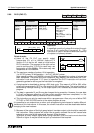
If the currentl
y
selected operatin
g
mode is
chan
g
ed before the ‘zero return complete’
fla
g
(M8043) is set, all outputs will be turned
OFF.
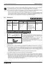
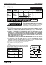
d) The ‘zero position’ is a term used to identif
y
a datum position from where the controlled
device, starts from and returns too after it
has completed its task. Hence, the operatin
g
mode ‘zero return’, causes the controlled
s
y
stem to return to this datum.
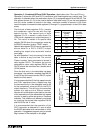
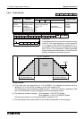
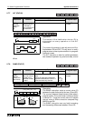
Mnemonic Function
Operands
Program steps
S
1
S
2
S
3
IST
FNC 60
(
Initial
state)
Automaticall
y
sets
up a multi-mode
STL operatin
g
s
y
stem
X, Y, M, S,
Note:
uses 8
consecutive devices
S,
Note:
FX
0
users S20 to S63
FX0N users S20 to S127
FX users S20 to S899
D1must be lower than D2
IST:
7 steps
M8000
S20X20 S40IST
[ S ] [ D1 ] [ D2 ]
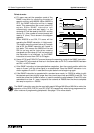
Assigned devices
Indirect user selected devices:
S
+0
Manual operation
S
+1
Zero return
S
+2
Step operation
S
+3
One cycle operation
S
+4
Cyclic operation
S
+5
Zero return start
S
+6
Automatic operation start
S
+7
Stop
Initial states:
S0 initiates ‘manual’ operation
S1 initiates ‘zero return’ operation
S2 initiates ‘automatic’ operation
General states:
S10 to S19 ‘zero return’ sequence
D
1
to D
2
‘automatic return’ sequence
Special bit flags:
M8040 = ON STL state transfer is inhibited
M8041 = ON initial states are enabled
M8042 = Start pulse given by start input
M8043 = ON zero return completed
M8044 = ON machine zero detected
M8047 = ON STL monitor enabled
The ‘zero’ position is sometimes also referred to as a home position, safe position, neutral
position or a datum position.