


FX Series Programmable Controlers Applied Instructions 5
5-104
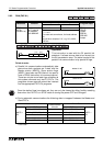
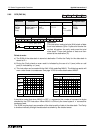
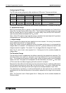
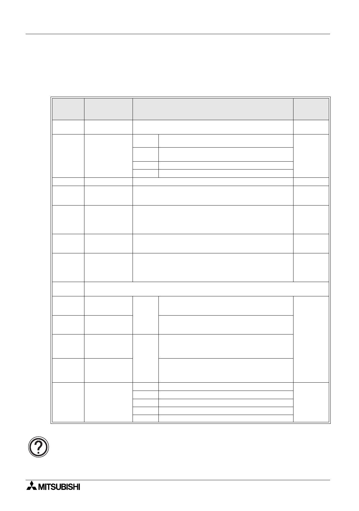
PID setup parameters;
S
3
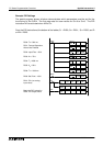
The PID setup parameters are contained in a 25 re
g
ister data stack. Some of these devices
require data input from the user, some are reserved for the internal operation and some return
output data from the PID operation.
Parameters S
3
+0 through S
3
+6 must be set by the user.
Parame-
ter
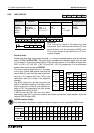
S3 + P
Parameter
name/function
Description
Setting
range
S
3
+0
Samplin
g
time
T
S
The time interval set between the readin
g
the current
Process Value of the s
y
stem (PV
nf
)
1 to 32767
msec
S
3
+1
Action - reaction
direction and
alarm control
b0
Forward operation(0),
Reverse operation (1)
Not
applicable
b1
Process Value (PV
nf
) alarm enable, OFF(0)/
ON(1)
b2 Output Value (MV) alarm enable, OFF(0)/ON(1)
b3 - 15 Reserved
S
3
+2
Input filter
α
Alters the effect of the input filter. 0 to 99%
S
3
+3
Proportional
g
ain
K
P
This is a factor used to ali
g
n the proportional output in a
known ma
g
nitude to the chan
g
e in the Process Value
(PV
nf
). This is the
P
part of the PID loop.
1 to
32767%
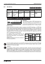
S
3
+4
Inte
g
ral time
constant
T
I
This is the
I
part of the PID loop.
This is the time taken for the corrective inte
g
ral value to
reach a ma
g
nitude equal to that applied b
y
the
proportional or
P
part of the loop.
Selectin
g
0 (zero) for this parameter disables the
I
effect.
(0 to 32767)
x 100 msec
S
3
+5
Derivative
g
ain
K
D
This is a factor used to ali
g
n the derivative output in a
known proportion to the chan
g
e in the Process Value
(PV
nf
)
1 to 100%
S
3
+6
Derivative time
constant
T
D
This is the
D
part of the PID loop.
This is the time taken for the corrective derivative value to
reach a ma
g
nitude equal to that applied b
y
the
proportional or
P
part of the loop.
Selectin
g
0 (zero) for this parameter disables the
D
effect.
(0 to 32767)
x 10 msec
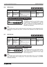
S
3
+7 to
S
3
+19
Reserved for use for the internal processin
g
S
3
+20
Process Value,
maximum
positive chan
g
e
Active
when
S
3
+1,
b1 is
set ON.
This is a user defined maximum limit for the
Process Value (PV
nf
). If the Process Value
(PV
nf
) exceeds the limit, S
3
+24, bit b0 is set On.
0 to 32767
S
3
+21
Process Value,
minimum value
This is a user defined lower limit for the Process
Value. If the Process Value (PV
nf
) falls below the
limit, S
3
+24, bit b1 is set On.
S
3
+22
Output Value,
maximum
positive chan
g
e
Active
when
S
3
+1,
b2 is
set ON.
This is a user defined maximum limit for the
quantit
y
of positive chan
g
e which can occur in
one PID scan. If the Output Value (MV) exceeds
this, S
3
+24, bit b2 is set On.
S
3
+23
Output Value,
maximum
ne
g
ative chan
g
e
This is a user defined maximum limit for the
quantit
y
of ne
g
ative chan
g
e which can occur in
one PID scan. If the Output Value (MV) falls
below the lower limit, S
3
+24, bit b3 is set On.
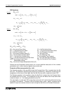
S
3
+24
Alarm fla
g
s
(Read Only)
b0
Hi
g
h limit exceeded in Process Value (PV
nf
)
Not
applicable
b1
Below low limit for the Process Value (PV
nf
)
b2 Excessive positive chan
g
e in Output Value (MV)
b3 Excessive ne
g
ative chan
g
e in Output Value (MV)
b4 - 15 Reserved
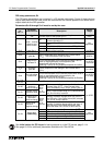
See
Initial values for PID loops
for basic
g
uidance on initial PID values; pa
g
e 5-114.
See pa
g
e 10-24 for additional parameters available with FX
2N
MPUs.