


FX Series Programmable Controllers Assigning System Devices 9
9-5
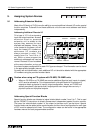
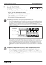
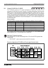
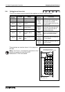
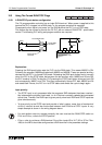
9.2.4 Using the FX
2
-24EI With A F
2
-30GM
The F
2
-30GM’s operational address is based upon the position of the associated FX
2
-24EI
within the users FX s
y
stem. However, the I/O numbers are not directl
y
affected b
y
this
operational address. The I/O numbers can be selected b
y
the user. The dia
g
ram on the pa
g
e
9-3 shows how movin
g
the position of the FX
2
-24EI used alters the operational address but
NOT the I/O numbers used b
y
the F
2
-30GM, see EX. 2A to 2C. Where the s
y
mbol § is used in
the dia
g
ram, this can be replaced b
y
the numbers ‘0’, ‘4’ or ‘5’. It is recommended that for
simplification the user favors ‘0’.
For details on usin
g
the F
2
-30GM see the units users manual. Please remember when readin
g
the manual, that it has been written for use on an F
2
s
y
stem and hence all of the I/O addresses
stated are for such an F
2
setup.
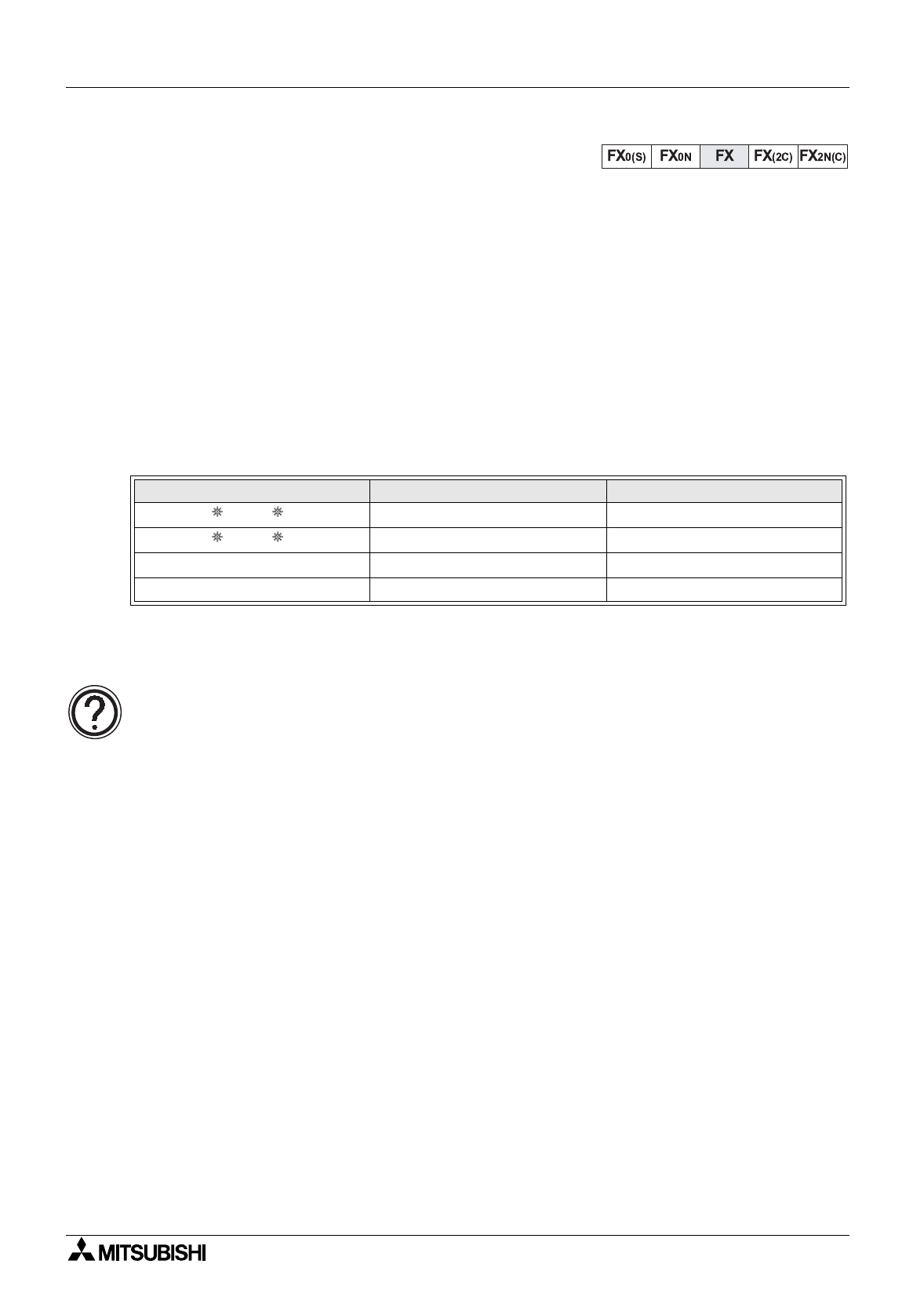
Worked example:
The followin
g
tabular example identifies the correspondence between FX and F
2
-30GM
s
y
stems.
The FX s
y
stem used is similar to that shown in the dia
g
ram EX. 2B from pa
g
e 9-3.
Applicable FX Applied Instructions:
(Not applicable to FX
2C
Main Processin
g
Units or FX units with CPU’s
g
reater than version
3.06)
• FNC 97, BLK - used to desi
g
nate a block number within the F
2
-30GM
• FNC 98, MCDE - used to read an M code number from the F
2
-30GM
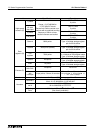
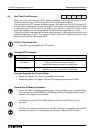
F2-30GM System Setup Comments FX System Setup
X 14 to X 27 Turn On
−
X54 to X67
Y 40 to Y 47 Are Turned On BY
−
Y40 to Y47
X0 to X6 No correspondence N/A
Y0 to Y6 No correspondence N/A