


FX Series Programmable Controllers Points Of Technique 10
10-6
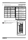
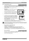
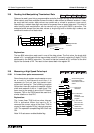
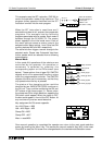
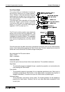
10.8 Reading And Manipulating Thumbwheel Data
Data can be easil
y
read into a pro
g
rammable controller throu
g
h the use of the BIN instruction.
When data is read from multiple sources the data is often stored at different locations. It ma
y
be required that certain data values are combined or mixed to produce a new value.
Alternativel
y
, a certain data di
g
it ma
y
need to be parsed from a lar
g
er data word. This kind of
data handlin
g
and manipulation can be carried out b
y
usin
g
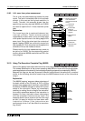
the SMOV instruction. The
example below shows how two data values (a sin
g
le di
g
it and a double di
g
it number) are
combined to make a final data value.
Explanation:
The two BIN instructions each read in one of the data values. The first value, the sin
g
le di
g
it
stored in D1, is combined with the second data value D2 (currentl
y
containin
g
2 di
g
its). This is
performed b
y
the SMOV instruction. The result is that the contents of D1 is written to the third
di
g
it of the contents of D2. The result is then stored back into re
g
ister D2.
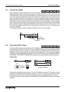
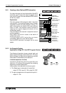
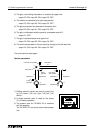
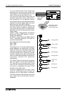
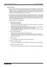
10.9 Measuring a High Speed Pulse Input
10.9.1 A 1 msec timer pulse measurement
Some times due to s
y
stem requirements or even
as a result of maintenance activities it is
necessar
y
to 'find out' how lon
g
certain input
pulses are lastin
g
for. The followin
g
pro
g
ram
utilizes two interrupt routines to capture a pulse
width and measure it with a 1 msec timer. The
timer used in the ample is one of the FX timers.
However, T63 on the FX0N would be used for a
similar situation on that PLC.
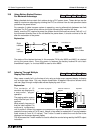
Explanation:
The 1 msec timer T246 is driven when interrupt
I001 is activated. When the input to X1 is
removed the current value of the timer T246 is
moved to data re
g
ister D0 b
y
interrupt pro
g
ram
I100. The operation complete fla
g
M0 is then set
ON.
Note: X10 acts as an enable/disable fla
g
.
M8000
SMOV D1 K1
BIN
K1
K2X20 D2
BIN K1X0 D1
D2 K3
657
X0 to X3 X20 to X27
D2 = 65
D1=7
D1- D2 D2=765
10
0
1
0
Digit
10
10
Digit
SMOV
FX prpgrammable
controller
X 10
S (X0, X1)
X 0 X 1
FEND
M8000
RST T246
X10
RST M 0
RST D 0
IRET
X10
D 0MOV T246
SET M 0
M0
K1
RST T246
M8000
IRET
END
I001
I100
T246
K32767
T246
General wiring-pluse
to be measured is
connected to both X0
and X1
Pulse to be
measured
EI instruction
MUST be
included in main
program
Pulse has been
measured
1 msec timer-
FX
0N
use T63
Measured time
stored inD0