FX Series Programmable Controllers Devices in Detail 4
4-34
4.12.1 General Use Registers
Data re
g
isters, as the name su
gg
ests, store data. The stored data can be interpreted as a
numerical value or as a series of bits, bein
g
either ON or OFF.
A sin
g
le data re
g
ister contains 16bits or one word. However, two consecutive data re
g
isters
can be used to form a 32bit device more commonl
y
known as a double word.
If the contents of the data re
g
ister is bein
g
considered numericall
y
then the Most Si
g
nificant Bit
(MSB) is used to indicate if the data has a positive or ne
g
ative bias. As bit devices can onl
y
be
ON or OFF, 1 or 0 the MSB convention used is, 0 is equal to a positive number and 1 is equal
to a ne
g
ative number.
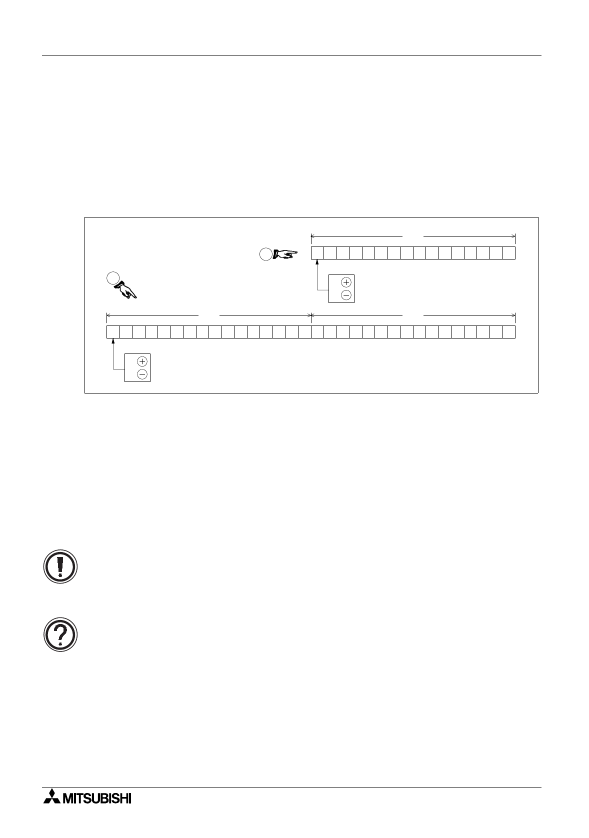
The dia
g
ram above shows both sin
g
le and double re
g
ister confi
g
urations. In the dia
g
ram
identified as
¡
, it should be noted that the ‘lower’ re
g
ister D0 no lon
g
er has a ‘Most Si
g
nificant
Bit’. This is because it is now bein
g
considered as part of a 32bit-double word. The MSB will
alwa
y
s be found in the hi
g
her 16 bits, i.e. in this case D1. When specif
y
in
g
a 32 bit data
re
g
ister within a pro
g
ram instruction, the lower device is alwa
y
s used e.
g
. if the above example
was to be written as a 32bit instructional operand it would be identified as D0. The second
re
g
ister, D1, would automaticall
y
be associated.
Once the data is written to a
g
eneral data re
g
ister, it remains unchan
g
ed until it is overwritten.
When the PLC is turned from RUN to STOP all of the
g
eneral data re
g
isters have their current
contents overwritten with a 0 (zero).
Data retention:
• Data can be retained in the
g
eneral use re
g
isters when the PLC is switched from RUN to
STOP if special auxiliar
y
rela
y
M8033 is ON.
Data register updates:
• Writin
g
a new data value to a data re
g
ister will result in the data re
g
ister bein
g
updated
with the new data value at the end of the current pro
g
ram scan.
D1 D0
D0
0:
1:
0:
1:
2
1
MSB - Most Significant Bit
MSB - Most Significant Bit


