


FX Series Programmable Controlers Applied Instructions 5
5-44
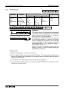
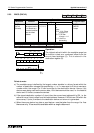
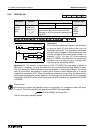
5.5.3 ENCO (FNC 42)
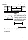
Operation:
The hi
g
hest active bit within the readable ran
g
e has
its location noted as a numbered offset from the
source head address (S). This is stored in the
destination re
g
ister (D).
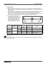
Points to note:
a) The readable ran
g
e is defined b
y
the lar
g
est number storable in a binar
y
format within the
number of destination stora
g
e bits specified b
y
n, i.e. if n was equal to 4 bits a maximum
number within the ran
g
e 0 to 15 can be written to the destination device. Hence, if bit
devices were bein
g
used as the source data, 16 bit devices would be used, i.e. the head bit
device and 15 further, consecutive devices.
b) If the stored destination number is 0 (zero) then the source head address bit is ON, i.e. the
active bit has a 0 (zero) offset from the head address. However, if NO bits are ON within the
source area, 0 (zero) is written to the destination device and an error is
g
enerated.
c) When the source device is a data or word device n must be taken from the ran
g
e 1
to 4 as
there are only 16 source bits available within a single data word.
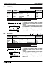
Mnemonic Function
Operands
Program steps
SD n
ENCO
FNC 42
(Encode)
Then location of
the hi
g
hest active
bit is stored as a
numerical position
from the head
address
X, Y, M, S,
T, C, D, V,
Z
T, C, D, V,
Z
K, H,
Note:
S=X, Y, M, S then
n ran
g
e=1-8
S= T,C,D then
n ran
g
e = 1-4
n = 0, then no
processin
g
ENCO,
ENCOP:
7 steps
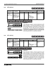
X5
D 10 K 3
[ S ] [ D ]
M 10
[ n ]
ENCO
M15 M14 M13 M12 M11 M10M16M17
01000 000
7. 6. 5. 4. 3. 2. 1. 0.
0 0 0 0 0 0 0 0 0 0 0 0 0 0 1 1
D10
421
..
+
= 3