


FX Series Programmable Controlers Applied Instructions 5
5-112
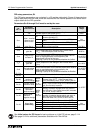
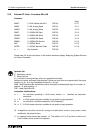
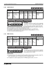
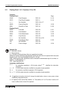
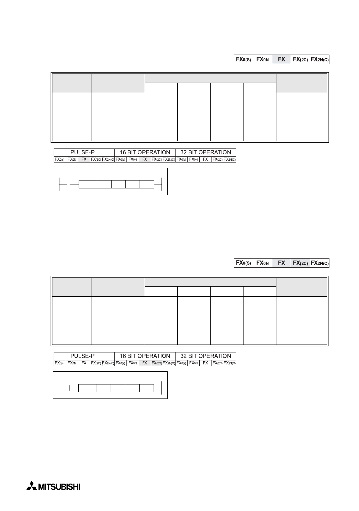
5.10.3 ANWR (FNC 92)
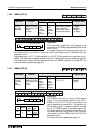
Operation:
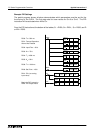
The ANWR instruction is used to write output data
to channel n of an F
2
-6A analo
g
module. The
written analo
g
value is stored in source device S
1
.
The head address I/O numbers for both S
2
and Dare determined b
y
the position of the FX
2
-
24EI (connected to the F
2
-6A) within the expansion chain.
The analo
g
data to be written is stored at the source device S
1
in an 8 bit format.
The operand nis used to specif
y
which analo
g
channel is bein
g
written to, i.e. 0 or 1.
For more information please see pa
g
e 9-4.
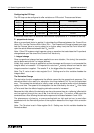
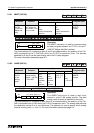
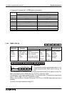
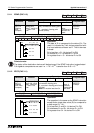
5.10.4 RMST (FNC 93)
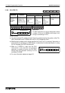
Operation:
The RMST instruction is used to start the operation
of an F
2
-32RM under FX control and to monitor the
current status of the F
2
-32RM.
Points to note:
a) The head address I/O numbers for both S
2
and Dare determined b
y
the position of the FX
2
-
24EI (connected to the F
2
-6A) within the FX PLC’s expansion chain.
b) The operand nis used to specif
y
which F
2
-32RM pro
g
ram is active, i.e. 0 or 1.
Mnemonic Function
Operands
Program steps
S
1
D
2
D
2
n
ANWR
FNC 92
(
F
2-
6A
Analo
g
write)
Used to write to
the F series
analo
g
module -
use
with an
FX
2
-24EI
KnY, KnM,
KnS, T, C,
D, V, Z
X
Note:
uses 8
consecu-
tive
devices
Y
Note:
uses 8
consecu-
tive
devices
K, H
Note:
n= 0 or 1
ANWR,
ANWRP:
9 steps
Mnemonic Function
Operands
Program steps
S
1
D
1
D
2
n
RMST
FNC 93
(
F
2
-32RM
RM start)
Used to start the
F series CAM
module - use with
an FX
2
-24EI
X
Note:
uses 8
consecu-
tive
devices
Y
Note:
uses 8
consecu-
tive
devices
Y, M, S
Note:
uses 8
consecu-
tive
devices
K, H
Note:
n= 0 or 1
RMST:
9 steps
X0
X40 Y30
[ D ]
K 0ANWR
[ S2 ]
D310
[ S1 ]
[ n ]
X0
Y30 M300
[ D2 ]
K 0RMST
[ D1 ]
X40
[ S ] [ n ]