


FX Series Programmable Controllers Assigning System Devices 9
9-2
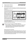
9.2 Using The FX2-24EI With F
Series Special Function Blocks
The FX
2
-24EI allows an FX base unit to be directl
y
connected to an one of the followin
g
F
series special function blocks:
a) The F-16NT/NP, a Melsec Net Mini interface
b) The F2-6A, a combine analo
g
4 input and 2 output unit
c) The F2-32RM, a pro
g
rammable CAM sequencer
d) The F2-30GM, a pulse train positionin
g
unit
One 24EI unit can control one F series special function unit.
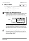
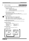
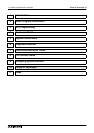
• The ‘24EI’ units are added to an FX s
y
stem in the same manner as an additional discreet
I/O module. Each 24EI occupies 16 input points and 8 output points, the dia
g
ram below
illustrates this point. Experienced users ma
y
notice that the example shown in the
dia
g
ram below would require too much power from the CPU unit (FX-48MR in this case)
based on the I/O count.
This is not the case. The FX2-24EI is reall
y
a communications module. It does not
directl
y
drive an
y
discreet I/O. For the sake of power calculations it can be assumed that
it onl
y
occupies 8 standard I/O points. This means that the confi
g
uration shown in the
dia
g
ram actuall
y
occupies 32 points (three FX2-24EI’s and one FX-8EX) of I/O for the
sake of power consumption calculations BUT actuall
y
occupies 80 points of addressable
I/O.
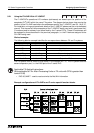
Connection Of Earth Points When Using F Series Special Function Blocks
• When usin
g
the F series special function blocks the special function blocks earth
terminal should be connected to the [SG] terminal of the FX CPU unit. However, when
usin
g
the F-16NP/NT unit the [SG] terminal of the F-16NP/NT should on
NO
account be
connected to the [SG] terminal of the FX. The function of these terminals are completel
y
different and are hence
NOT
compatible.
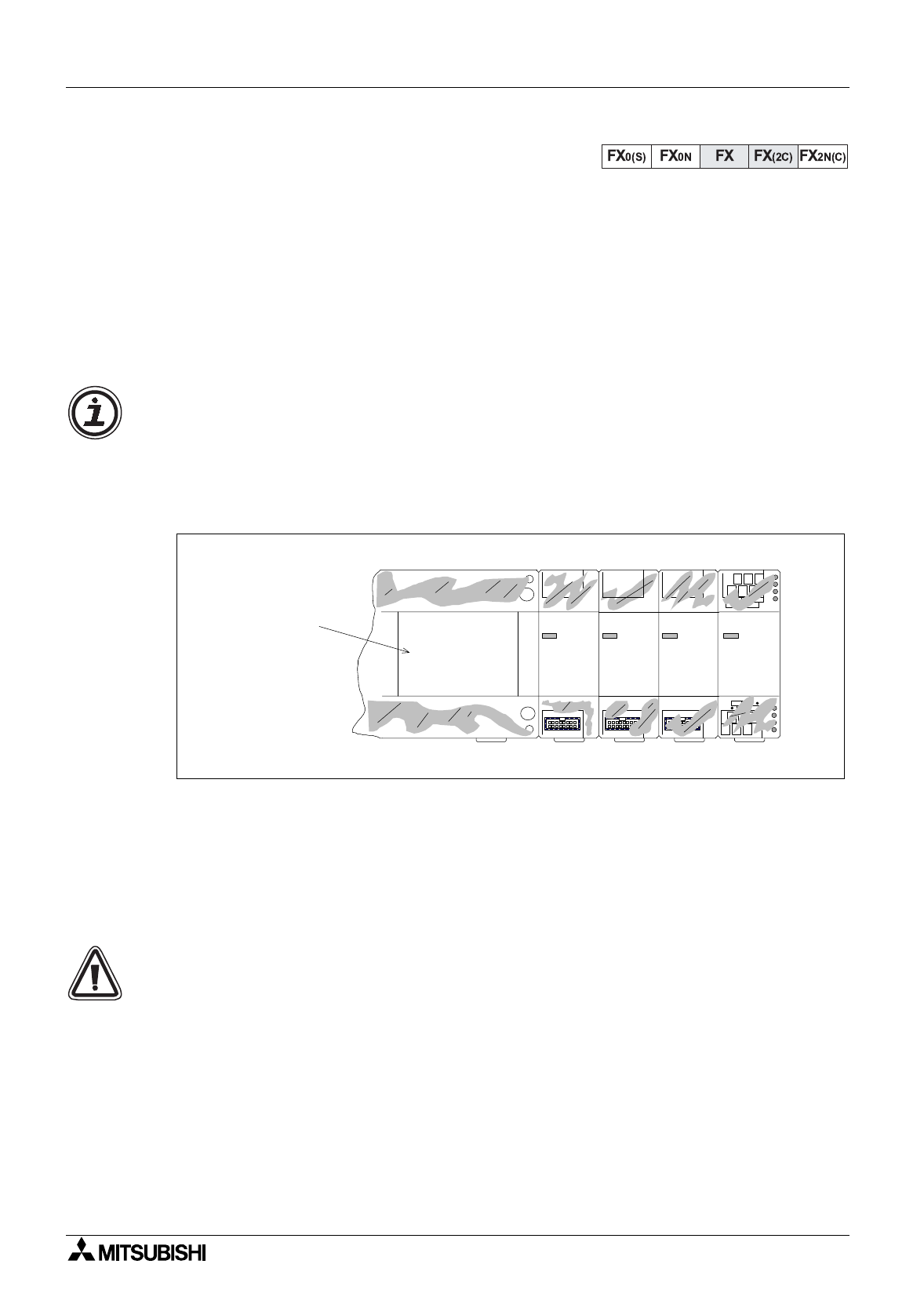
POWER
FX -24EI
2
POWER
FX -24EI
2
POWER
FX -24EI
2
POWER
FX-8EX
X30-47
Y30-37
X40-57
Y40-47
X50-57
Y50-57
X110-
Y117
Inputs X0-27
FX-48MR
Outputs Y0-27