


FX Series Programmable Controllers Basic Program Instructions 2
2-6
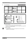
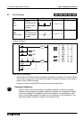
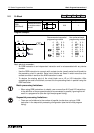
2.6 And, And Inverse
Pro
g
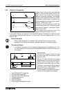
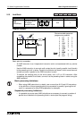
ram example:
Basic points to remember:
- Use the AND and ANI instructions for serial connection of contacts. As man
y
contacts as
required can be connected in series (see followin
g
point headed “Peripheral limitations”).
- The output processin
g
to a coil, throu
g
h a contact, after writin
g
the initial OUT instruction
is called a “follow-on” output (for an example see the pro
g
ram above; OUT Y4). Follow-
on outputs are permitted repeatedl
y
as lon
g
as the output order is correct.
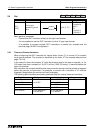
Mnemonic Function Format Devices Program steps
AND
(AND)
Serial connection
of NO (normall
y
open) contacts
X, Y, M, S, T, C 1
ANI
(AND Inverse)
Serial connection
of NC (normall
y
closed) contacts
X, Y, M, S, T, C 1
X
X
Y
Y
X
M
T
Y
X2
Y3
AND
X0
X3
T1
ANI
AND
2
0
3
3
3
101
1
4
LD
AND
OUT
LD
ANI
OUT
OUT
AND
0
1
2
3
4
6
7
5
Y3
M101
Y4
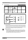
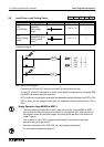
Peripheral limitations:
• The PLC has no limit to the number of contacts connected in series or in parallel.
However, some pro
g
rammin
g
panels, screens and printers will not be able to displa
y
or print the pro
g
ram if it exceeds the limit of the hardware. It is preferable for each
line or run
g
of ladder pro
g
ram to contain up to a maximum of 10 contacts and 1 coil.
Also, keep the number of follow-on outputs to a maximum of 24.