


FX Series Programmable Controller Diagnostic Devices 6
6-2
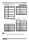
6.1 PLC Status (M8000 to M8009 and D8000 to D8009)
Diagnostic
Device
Operation
Diagnostic
Device
Operation
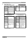
M8000 (
)
RUN monitor
NO contact
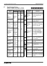
D8000 ( )
Watchdo
g
timer
FX, FX
2C
: 100ms
FX
0
, FX
0S
, FX
0N
, FX
2N
: 200ms
See note 1
M8001 (
)
RUN monitor
NC contact
D8001 ( )
PLC t
y
pe and
version
20Vvv FX
0(S)
, FX
0N
, FX, FX
2C
version V.vv
24Vvv: FX
2N
version V.vv
M8002 (
)
Initial pulse
NO contact
D8002 ( )
Memor
y
capacit
y
0002: 2K steps
0004: 4K steps
0008: 8K steps
(see also D8102)
M8003 (
)
Initial pulse
NC contact
D8003 (
)
Memor
y
t
y
pe
00H = RAM, 01H = EPROM,
02H = EEPROM,
0AH = EEPROM (protected)
10H = MPU memor
y
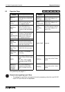
M8004 ( )
Error
occurrence
ON when one or more error
fla
g
s from the ran
g
e M8060
to M8067 are ON
D8004 (
)
Error number
M
The contents of this re
g
ister
identifies which error
fla
g
is active, i.e. if =
8060 identifies M8060
M8005
Batter
y
volta
g
e Low
On when the batter
y
volta
g
e
is below the value set in
D8006
D8005
Batter
y
volta
g
e
E.
g
. 36 = 3.6 volts
M8006
Batter
y
error
latch
Latches the batter
y
Low
error
D8006
Low batter
y
volta
g
e
The level at which a batter
y
volta
g
e low is detected
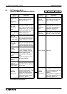
M8007
Momentar
y
power failure
D8007
Power failure
count
The number of time a momen-
tar
y
power failure has occurred
since power ON.
M8008
Power failure
Power loss has occurred
D8008
Power failure
detection
The time period before shut
down when a power failure
occurs (default 10ms)
M8009
24V DC Down
Power failure of 24V DC
service suppl
y
D8009
24V DC
failed device
Lowest device affected b
y
24V
DC power failure
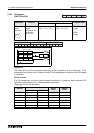
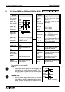
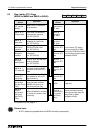
RUN
Input
M8061 error occurence
M8000
M8001
M8002
M8003
Program scan time
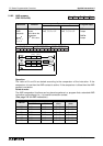
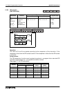
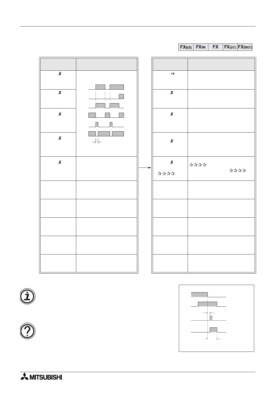
AC
Power
M8000
M8007
Approx. 5msec
Momentry power failure
M8008
Power failure
D8008
10msec
(Power failure
detection period)
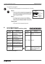
For symbol key see page 6-1.
Note 1:
• The contents of this re
g
ister can be chan
g
ed b
y
the
user. Settin
g
s in 1 msec steps are possible. The
value should be set
g
reater than the maximum scan
time (D8012) to ensure constant scan operation.
General note:
• When the power suppl
y
used is 200V AC, the power
down detection period is determined b
y
the value of
D8008. This can be altered b
y
the user within the
allowable ran
g
e of 10 to 100msec.