


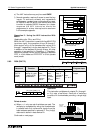


FX Series Programmable Controlers Applied Instructions 5
5-86
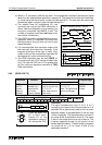
d) If the SEGL instruction is suspended durin
g
mid-operation, when it is restarted it will start
from the be
g
innin
g
of its c
y
cle and not from its last status achieved.
e) The SEGL instruction ma
y
be used
ONCE
on FX controllers with CPU versions lower than
3.07. FX units with CPU ver 3.07 or
g
reater and all FX
2C
units can operate a maximum of
TWO
SEGL instructions.
Selecting the correct value for operand n
The selection of parameter n depends on 4 factors;
1) The lo
g
ic t
y
pe used for the PLC output
2) The lo
g
ic t
y
pe used for the seven se
g
ment data lines
3) The lo
g
ic t
y
pe used for the seven se
g
ment strobe si
g
nal
4) How many sets of displays are to be used
There are two t
y
pes of lo
g
ic s
y
stem available, positive lo
g
ic and ne
g
ative lo
g
ic. Dependin
g
on
the t
y
pe of s
y
stem, i.e. which elements have positive or ne
g
ative lo
g
ic the value of n can be
selected from the table below with the final reference to the number of sets of seven se
g
ment
displa
y
s bein
g
used:
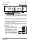
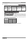
Device considered Positive logic Negative logic
PLC Logic
With a source output, when the
output is HIGH the internal lo
g
ic is ‘1’
With a sink output, when the output
is LOW the internal lo
g
ic is ‘1’
Seven
segment
Display
logic
Strobe
si
g
nal lo
g
ic
Data is latched and held when this
si
g
nal is HIGH, i.e. its lo
g
ic is ‘1’
Data is latched and held when this
si
g
nal is LOW, i.e. its lo
g
ic is ‘1’
Data
si
g
nal lo
g
ic
Active data lines are held HIGH,
i.e. the
y
have a lo
g
ic value of ‘1’
Active data lines are held LOW, i.e.
the
y
have a lo
g
ic value of ‘1’
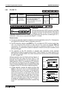
PLC Logic
Seven segment display logic n
Data Logic Strobe logic 1 display set 2 display sets
Positive
(Source)
Positive
(High)
Positive
(High)
04
Ne
g
ative
(Sink)
Ne
g
ative
(Low)
Ne
g
ative
(Low)
Positive
(Source)
Positive
(High)
Ne
g
ative
(Low)
15
Ne
g
ative
(Sink)
Ne
g
ative
(Low)
Positive
(High)
Positive
(Source)
Positive
(High)
Ne
g
ative
(Low)
26
Ne
g
ative
(Sink)
Ne
g
ative
(Low)
Positive
(High)
Positive
(Source)
Positive
(High)
Positive
(High)
37
Ne
g
ative
(Sink)
Ne
g
ative
(Low)
Ne
g
ative
(Low)
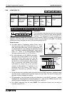
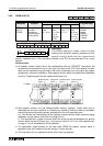
V+
0V
Y
+V1
HIGH
Pull-down
Source output
COM
Y
V+
0V
LOW
Pull-up
resistor
Sink output