


FX Series Programmable Controllers Points Of Technique 10
10-7
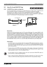
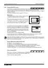
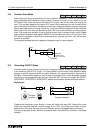
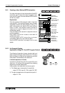
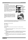
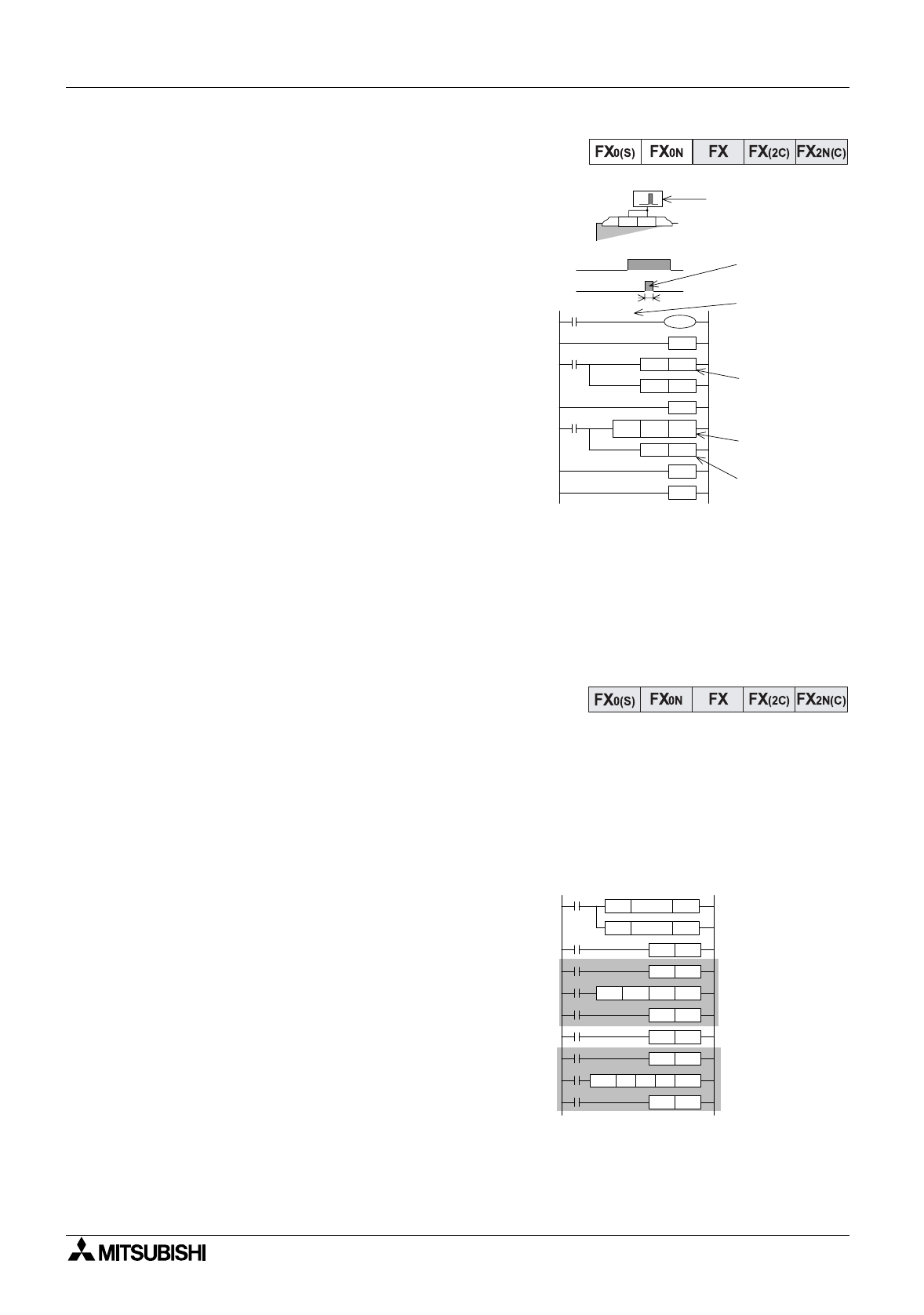
10.9.2 A 0.1 msec timer pulse measurement
This is a ver
y
accurate measurin
g
process for pulse
inputs. The use of a standard timer is not accurate
enou
g
h in this case as the hi
g
hest resolution is
1msec. Therefor, this example shows how the
special hi
g
h accurac
y
devices M8099 and D8099
are used to capture the 0.1 msec resolution pulse
data.
Explanation:
The incomin
g
pulse is captured between two
interrupt routines. These routines operate
independentl
y
of each other, one on the risin
g
ed
g
e
of the pulse input and one on the fallin
g
ed
g
e of the
same input. Durin
g
the pulse input the contents of
special re
g
ister D8099 are continuall
y
moved into
data re
g
ister D0. Once the pulse has completed the
contents of D0 can be viewed at leisure.
Please note for this hi
g
h speed/accurac
y
mode to
be active for D8099, the correspondin
g
special
auxiliar
y
bit device M8099 must be driven ON in the
main pro
g
ram.
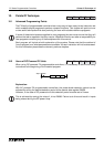
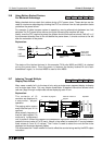
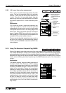
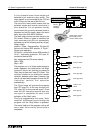
10.10 Using The Execution Complete Flag, M8029
Some of the applied instructions take more than one pro
g
ram scan to complete their operation.
This makes identification of the current operatin
g
state difficult. As an aid to the pro
g
rammer,
certainappliedinstructionsidentif
y
theircompletionb
y
settin
g
anoperationcompletefla
g
, M8029.
Because this fla
g
can be used b
y
several different instructions at the same time, a method
similar to the followin
g
should be used to trap the M8029 status at each of the instructions
usin
g
it:
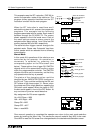
Explanation:
The M8029 'trappin
g
’ sequence takes advanta
g
e of
the batch refresh of the FX famil
y
of PLC’s. As the
pro
g
ram scan passes each instruction usin
g
M8029
the status of M8029 chan
g
es to reflect the current
status of the instruction. Hence, b
y
immediatel
y
resettin
g
(or settin
g
) the drive fla
g
for the instruction
the current operational status of the instruction is
trapped. So when the batch refresh takes place
onl
y
the completed instructions are reset. The
example above uses a pulse to set the drive fla
g
s
so that it is eas
y
to monitor and see when each
instruction finishes (if the instructions are
continuousl
y
driven it will be difficult to see when
the
y
finish!).
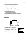
General wiring-pluse
to be measured is
connected to both X0
and X1
Pulse to be
measured
EI instruction
MUST be
included in main
program
Pulse has been
measured
Special device
D8099
Measured time
stored inD0
FEND
X10
X10
RST D8099
RST M 0
IRET
X10
D 0MOV D8099
SET M 0
IRET
END
X 10
S (X0, X1)
I001
I100
M8099
X 0 X 1
M8002
X0
D 0MOV
D2
K 32766
MOV
K 0
M100PLS
M100
Y5SET
K100
K10PLSY
Y0
Y5
M8029
Y5RST
M101PLS
M101
Y6SET
Y6
M8029
Y6RST
X1
D2D0
RAMP
D3
K8000
Trapped
instruction
Trapped
instruction