


FX Series Programmable Controllers Points Of Technique 10
10-24
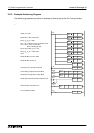
10.15 PID Programming Techniques
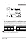
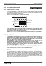
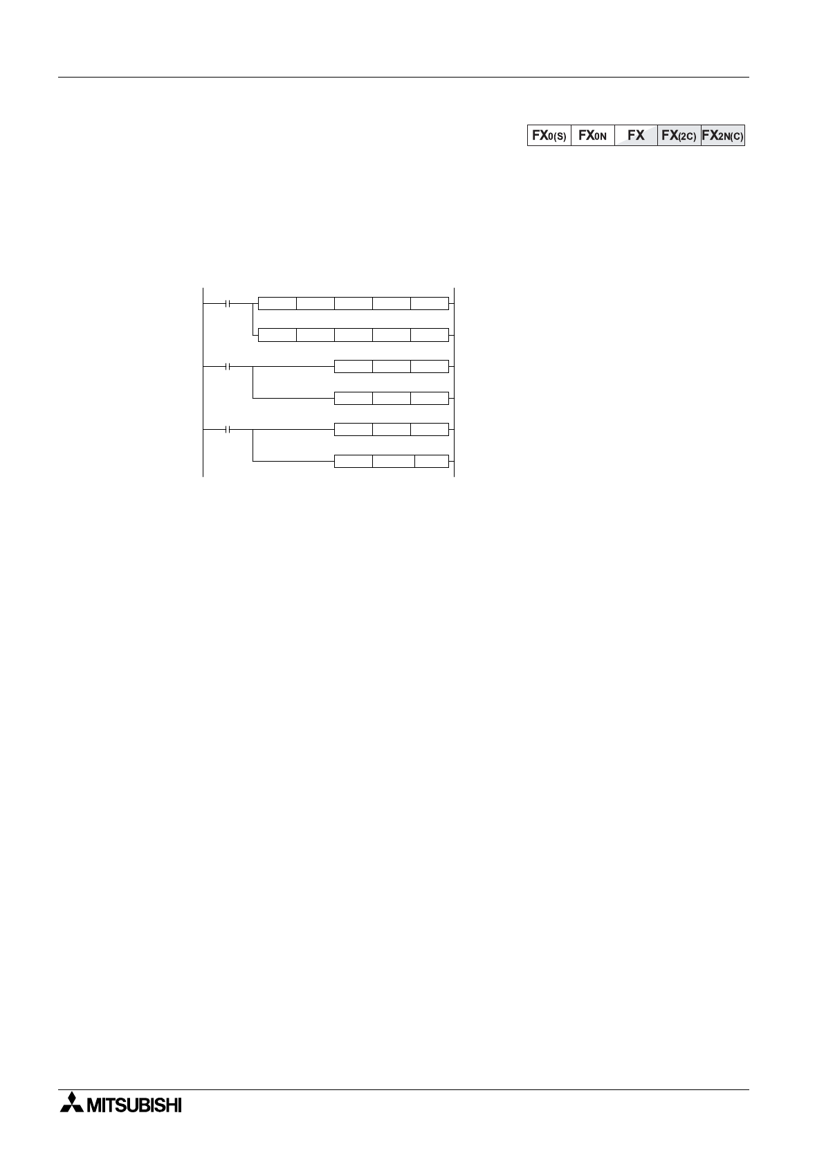
10.15.1 Keeping MV within a set range
In the reserved re
g
isters of the PID data block S
3
+18 and S
3
+19 form a double word device
that contains the previous MV x K100. The followin
g
pro
g
ram uses this to keep MV under
control when it exceeds the operatin
g
limits.
Example Pro
g
ram to keep MV in the ran
g
e K100 to K5000
If data re
g
isters are used to hold the limit values, it is possible to use a MUL instruction instead
of the DMOV. E.
g
. When D50 is upper limit use: MUL D50 K100 D38 because the result of
MUL is alread
y
a double word DMUL is not needed.
Resettin
g
(S
3
+19, S
3
+18) in this wa
y
prevents runawa
y
, which occurs if onl
y
MV is chan
g
ed.
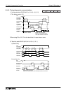
10.15.2 Manual/Automatic change over
In order to switch from automatic (PID) control to manual control and back to automatic it is
necessar
y
for the PID process to perform 'Manual Trackin
g
'. Althou
g
h the FX PID instruction
does not have a manual trackin
g
feature there are two methods that can be used to make the
switch from manual back to automatic as trouble free as possible.
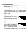
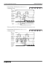
To understand the reason for the two methods the followin
g
should be noted. The PID
instruction sets its initial output value based on the initial value of the output re
g
ister.
When the PID instruction is switched on it can onl
y
do P as it has onl
y
1 data readin
g
. On the
first readin
g
the current value of the output re
g
ister is used as
∆
MV. Thereafter the previous
output value is used (stored in S
3
+18, S
3
+19).
After the next readin
g
PI can be calculated and from the third readin
g
full PID is performed.
Please see section 5.98, PID (FNC 88), for the complete equations.
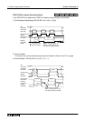
Method 1
It is recommended that if manual to auto switchin
g
is desired that the PID instruction is
switched off durin
g
manual operation and the operator controls the value of the MV re
g
ister
(the Output Value). When returnin
g
to auto mode, the PID instruction is switched on a
g
ain and
uses the last MV input b
y
the operator durin
g
the first PID calculation. After 3 readin
g
s full PID
will be operatin
g
and the process should be under control quickl
y
. (Assumin
g
that manual
control did not cause a move too far from the Set Point.)
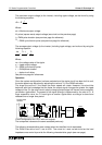
X10
D18 D19 D20 D46PID
K100 K5000 D46 M20ZCP
M20
K100 D46MOV
K10000 D38DMOV
M22
K5000 D46MOV
K500000 D38DMOV
SV
PV
Data
Block
MV
MV
MV
MV
MV
n-1
x
K100
MV
n-1
x
K100
Below
Lower Limit
Above
Upper Limit
Reset PID data to upper limit
MV > 5000: Fix MV to upper limit
Reset PID data to lower limit
MV < 100: Fix MV to lower limit
Check MV against range