


FX Series Programmable Controlers Applied Instructions 5
5-57
5.6.6 HSZ (FNC 55)
Operation 1 - Standard:
(Applicable to all units)
This instruction works in exactl
y
the same wa
y
as
the standard ZCP (FNC11). The onl
y
difference is
that the device bein
g
compared is a hi
g
h speed
counter (specified as S
3
).
Also, all of the outputs (D) are updated immediatel
y
due to the interrupt operation of the DHSZ.
It should be remembered that when a device is specified in operand D it is in fact a head
address for 3 consecutive devices. Each one is used to represent the status of the current
comparison, i.e. usin
g
the above example as a basis,
Y10 (D) C251 is less than S
1,
K1000 (S
3
< S
1)
Y11 (D
+1)
C251 is
g
reater than S
1,
K1000 but less than S
2,
K1200 (S
3
> S
1
, S
3
< S
2
)
Y12 (D
+2)
C251 is
g
reater than S
2,
K1200 (S
3
> S
2)
Operation 2 - Using HSZ With A Data Table:
(Applicable units: FX
(2C)
and FX
2N
)
Operation 2 is selected when the destination device (D) is assi
g
ned special M coil M8130. This
then allows devices (S
1
, S
2
) to be used to define a data table usin
g
(S
1
) as the head address
and (S
2
) as the number of records in the table - maximum number of records is 128. Each
record occupies 4 consecutive data re
g
isters proportioned in
the followin
g
manner (for a
sin
g
le record of data re
g
isters D throu
g
h D
+3
):
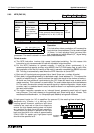
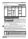
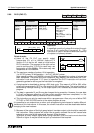
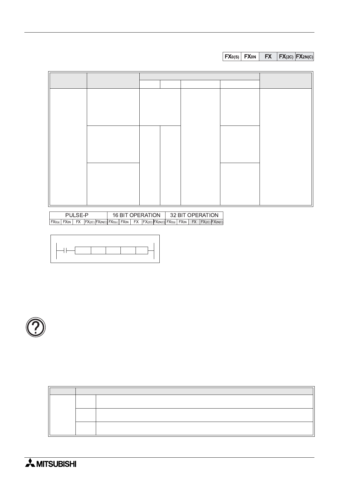
Mnemonic Function
Operands
Program steps
S
1
S
2
S
3
D
HSZ
FNC 55
(Hi
g
h
speed zone
compare)
Operation 1:
The current value
of a hi
g
h speed
counter is checked
a
g
ainst a specified
ran
g
e
K, H,
KnX, KnY,
KnM, KnS,
T, C, D, V, Z
C
Note:
C = 235 to
255,
Y, M, S
Note:
3 consecutive
devices are
used
DHSZ:
17 steps
Operation 2:
The desi
g
nated
ran
g
e is held in a
data table drivin
g
‘Y’ outputs directl
y
DK,H
Usin
g
values
from
1 to
128
(deci-
mal)
M8130 (onl
y
)
This fla
g
can
onl
y
be used
with one
DHSZ
instr’ at a time
Operation 3:
The desi
g
nated
ran
g
e is held in a
data table drivin
g
PLSY frequencies
directl
y
usin
g
D8132
M8132 (onl
y
)
This fla
g
can
onl
y
be used
with one
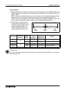
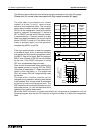
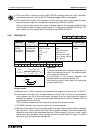
Single Record
Data
re
g
isters
D,
D
+1
Used as a double (32 bit) data re
g
ister to contain the comparison data
D
+2
Stores the I/O device number, in HEX, of the ’Y’ Output device to be controlled, i.e.
H10=Y10. Note: Hex di
g
its A throu
g
h F are not used.
D
+3
Stores the action (SET/RESET) to be performed on the Output device D
+2
. Note:
For a SET (ON) operation D
+3
must equal 1, for a RESET (OFF) D
+3
must equal 0.
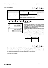
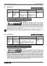
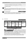
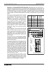
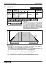
M8000
C251 Y10
K1000
DHSZ
K1200
[ S1 ] [ S2 ] [ S3 ] [ D ]
For further,
g
eneral points, about usin
g
hi
g
h speed counter functions please see the
subsection ‘Points to note’ under the HSCS (FNC 52). Relevant points are; a, b, and c. Please
also reference the note about the number of hi
g
h speed instructions allowable.