


FX Series Programmable Controlers Applied Instructions 5
5-107
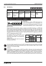
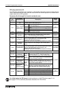
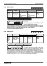
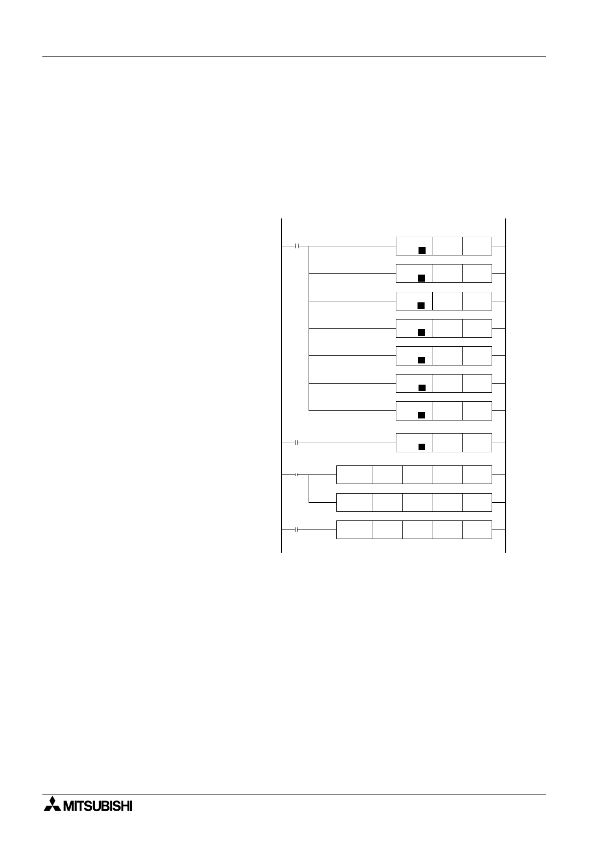
Example PID Settings
The partial pro
g
ram shown at below demonstrates which parameters must be set for the
functionin
g
of the FX2N. The first step sets the user values for S
3
+0 to S
3
+6. The PID
instruction will be activated when M4 is On.
From the PID instruction at the bottom of the ladder, S
1
= D200; S
2
= D201; S
3
= D500; and D
or MV = D525.
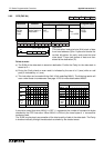
K500 D500
FNC 12
MOV
P
H0000 D501
FNC 12
MOV
P
K50 D502
FNC 12
MOV
P
K75 D503
FNC 12
MOV
P
K50 D505
FNC 12
MOV
P
K3000 D506
FNC 12
MOV
P
K2000 D504
FNC 12
MOV
P
M8002
K 1000 D200
FNC 12
MOV
P
M4
FNC 88
PID
D200 D201 D500 D525
M1
FNC 79
TO
K2 K1 K4 K4
FNC 78
FROM
K2 K5 D201 K4
M8002
D500: Ts = 500 ms
D501: Forward Operation,
Alarms Not Enabled
D502: Input Filter = 50%
D503: K
P
= 75%
D504: T
I
= 4000 ms
D505: K
D
= 50%
D506: T
D
= 1000 ms
D200: Set Point = 1000
D201: PV
nf
(an analog
input value)
Begin the PID instruction
D525: PID Output Value