


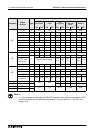

FX Series Programmable Controllers Execution Times And Instructional Hierarchy 7
7-10
1:
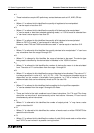
• These instructions require NO preliminar
y
contact devices such as LD, AND, OR etc.
2:
• Where “n” is referred to this identifies the quantit
y
of re
g
isters to be manipulated.
“n” can be equal or less than 512.
3:
• Where “n” is referred to this identifies the quantit
y
of bit devices to be manipulated.
“n” can be equal or less than selected operatin
g
mode, i.e. if 32 bit mode is selected then
“n” can have a value equal or less than 32.
4:
• Where "n" is referred to this identifies the quantit
y
of bit devices to be manipulated.
When an FX PLC is used "n" can be equal or less than 1024.
However, when FX0 and FX0N controllers are used "n" can be equal or less than 512.
5:
• Where "n" is referred to this identifies the quantit
y
devices to be manipulated. "n" can have
an
y
value taken from the ran
g
e 2 throu
g
h 512.
6:
• Where "n" is referred to this identifies the ran
g
e of devices to be reset. The device t
y
pe
bein
g
reset is identified b
y
the device letter in brackets in the '16/32 bit' column.
7:
• Where "n" is referred to this identifies the number of devices the mean is to be calculated
from. The value of "n" can be taken from the ran
g
e 1 throu
g
h 64.
8:
• Where "n" is referred to this identifies the ran
g
e of devices to be refreshed. The value of "n"
is alwa
y
s specified in units of 8, i.e 8, 16, 24.....128. The maximum allowable ran
g
e is
dependent on the number of available inputs/outputs, i.e. FX0 is limited to 16 as a
maximum batch that can be refreshed, where as FX can use 128.
9:
• Where "n" is referred to this identifies the time settin
g
for the input filters operation.
"n" can be selected from the ran
g
e 0 throu
g
h to 60 msec.
10:
• There are limits to the total combined use of these instructions. For FX
0
and FX
0N
there
should be no more than 4 simultaneousl
y
active instructions. However, FX can have 6
simultaneousl
y
active instructions.
11:
• Where "n" is referred to this identifies the number of output points. "n" ma
y
have a value
equal or less than 64.
12:
• Where "n" is referred to this identifies the number of words read or written FROM/TO the
special function blocks.
13:
• Where "n" is referred to this identifies the number of octal (8 bit) words read or written when
two FX PLC’s are involved in a parallel runnin
g
function.