


FX Series Programmable Controlers Applied Instructions 5
5-85
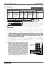
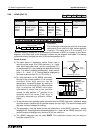
5.8.5 SEGL (FNC 74)
Operation:
This instruction takes a source decimal value (S)
and writes it to a set of 4 multiplexed, outputs (D).
Because the lo
g
ic used with latched seven
se
g
ment displa
y
s varies between displa
y
manufactures, this instruction can be modified to suit
most lo
g
ic requirements. Confi
g
urations are selected dependin
g
on the value of n, see the
followin
g
pa
g
e.
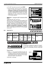
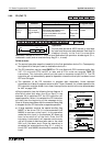
Points to note:
a) Data is written to a set of multiplexed outputs (D
+0
to D
+7
, 8 outputs) and hence seven
se
g
ment displa
y
s. A set of displa
y
s consists of 4 sin
g
le di
g
it seven se
g
ment units. A
maximum of two sets of displa
y
s can be driven with this instruction. When two sets are used
the displa
y
s share the same strobe outputs (D
+4
to D
+7
are the strobe outputs). An
additional set of 4 output devices is required to suppl
y
the new data for the second set of
displa
y
s (D
+10
to D
+13
, this is an octal addition). The strobe outputs cause the written data to
be latched at the seven se
g
ment displa
y
.
b) Source data within the ran
g
e of 0 to 9,999 (decimal) is written to the multiplexed outputs.
When one set of displa
y
s are used this data is taken from the device specified as operand
S. When two sets of displa
y
s are active the source device S
+1
supplies the data for the
second set of displa
y
s. This data must a
g
ain be within the ran
g
e 0 to 9,999. When usin
g
two sets of displa
y
s the data is treated as
two
separate numbers and is
not
combined to
provide a sin
g
le output of 0 to 99,999,999.
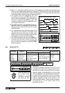
c) The SEGL instruction takes 12 pro
g
ram scans to complete one output c
y
cle re
g
ardless of
the number of displa
y
sets used. On completion, the execution complete fla
g
M8029 is set.
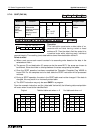
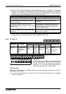
Mnemonic Function
Operands
Program steps
SD n
SEGL
FNC 74
(
Seven
se
g
ment
with latch)
Writes data to
multiplexed sin
g
le
di
g
it displa
y
s - 4
di
g
its per set,
max. 2 sets
K, H
KnX, KnY,
KnM, KnS
T, C, D, V, Z
Y
Note:
n = 0 to 3, 8
outputs are
used
n = 4 to 7, 12
outputs are
used
K, H,
Note:
n= 0 to 3, 1 set
of 7 Se
g
active
n= 4 to 7, 2 sets
of 7 Se
g
active
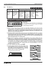
SEGL:
7 steps
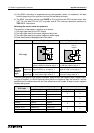
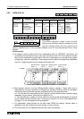
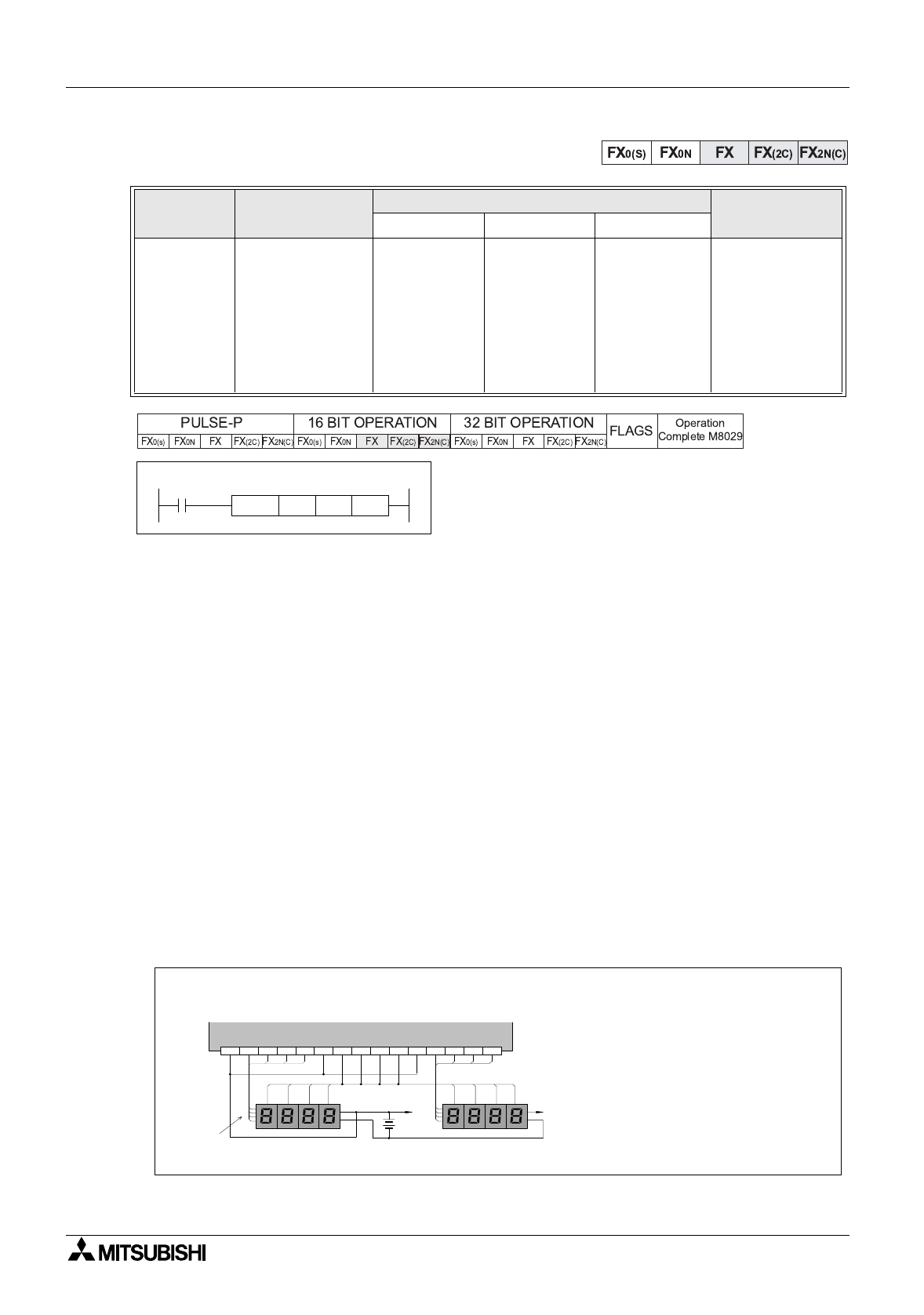
X0
D 0 Y 0 K 4SEGL
[ D ][ S ] [ n ]
10101010
3012
Y2 Y3+V0 Y0 Y1 Y6 Y7+V1 Y4 Y5 Y12 Y13+V2 Y10 Y11
1248
10
10
1010
30
1
2
V+
V+
1
2
4
8
1
2
4
8
1248
Transistor Output (Source)
BCD
data
signals
Display set 2
Display set 1
In this example it has
been assumed that the
seven se
g
ment displa
y
s
accept data HIGH inputs
and latch when a HIGH
si
g
nal is received
Note: A sin
g
le set of strobe si
g
nals are alwa
y
s used
re
g
ardless of the number of displa
y
sets.