


FX Series Programmable Controllers STL Programming 3
3-9
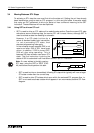
3.5.2 Single Signal Step Control
Transferrin
g
between active STL steps can be controlled b
y
a sin
g
le si
g
nal. There are two
methods the user can pro
g
ram to achieve this result.
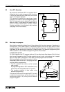
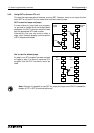
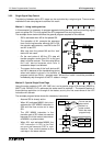
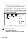
Method 1 - Using locking devices
In this example it is necessar
y
to pro
g
ram separate lockin
g
devices, and the controllin
g
si
g
nal
must onl
y
pulse ON. This is to prevent the STL pro
g
rams from runnin
g
throu
g
h.
The example shown below identifies the
g
eneral pro
g
ram required for this method.
- S30 is activated when M0 is first pulsed ON.
- The operation of M1 prevents the sequence
from continuin
g
because althou
g
h M0 is ON,
the transfer requirements, need M0 to be ON
and M1 to be OFF.
- After one scan the pulsed M0 and the ‘lock’
device M1 are reset.
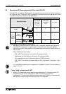
- On the next pulse of M0 the STL step will
transfer pro
g
ram control from S31 to the next
step in a similar manner. This time usin
g
M2 as
the ‘lock’ device because dual coils in
successive steps is not allowed.
- The reason for the use of the ‘lock’ devices M1
and M2 is because of the handshakin
g
period
when both states involved in the transfer of
pro
g
ram control are ON for 1 pro
g
ram scan. Without the ‘locks’ it would be possible to
immediatel
y
skip throu
g
h all of the STL states in one
g
o!
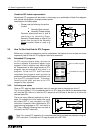
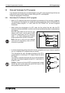
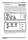
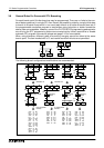
Method 2 - Special Single Pulse Flags
Usin
g
the pulse contacts (LDP, LDF, ANP, etc.) and a special ran
g
e of M devices (M2800 to
M3071) the FX2N(C) PLC’s achieves the same result as method 1. The special feature of
these devices prevents run throu
g
h of the states, as onl
y
the first occurrence of the LDP
instruction will activate.
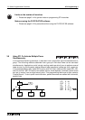
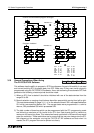
The example pro
g
ram below shows the necessar
y
instructions.
- Assume S50 is alread
y
active.
- When X01 activates M2800, this in turn
activates the LDP M2800 instruction in
S50 and the flow moves on to step
S51.
- The LDP M2800 instruction in the
transition part of S51 does not execute
because this is the second occurrence
of M2800 in a pulse contact.
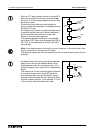
- When X01 next activates M2800, the
LDP instruction in S51 is the first
occurrence because S50 is now
inactive. Thus, control passes to the
next step in the same manner.
M1PLS
M0
S 30
S 31
M2PLS
M1
M2
M0
M0
S 50
S 51
M2800
M2800
LAD0
M2800
M2800
M2800
X001
SET S51
M2800
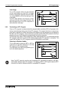
SET Snn
M2800
Do not use the
step control
device in a
pulse contact
within the main
pro
g
ram body.