


FX Series Programmable Controlers Applied Instructions 5
5-84
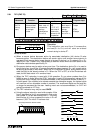
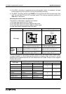
b) When n= 2, two sets of switches are read. This confi
g
uration requires 8 consecutive inputs
taken from the head address specified in operand S. The data from the first set of switches,
i.e. those usin
g
the first 4 inputs, is read into data device D
2
. The data from the second set
of switches (a
g
ain 4 di
g
its) is read into data device D
2+1
.
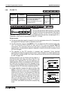
c) The outputs used for multiplexin
g
(D
1
) are
c
y
cled for as lon
g
as the DSW instruction is
driven. After the completion of one readin
g
, the
execution complete fla
g
M8029 is set. The
number of outputs used does
not
depend on
the number of switches n.
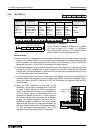
d) If the DSW instruction is suspended durin
g
mid-
operation, when it is restarted it will start from
the be
g
innin
g
of its c
y
cle and not from its last
status achieved.
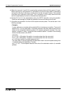
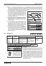
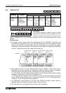
e) It is recommended that transistor output units
are used with this instruction. However, if the
pro
g
ram technique at the ri
g
ht is used, rela
y
output units can be successfull
y
operated as
the outputs will not be continuall
y
active.
f) The DSW instruction ma
y
be used
ONCE
on
FX controllers with CPU versions lower than
3.07. FX units with CPU ver 3.07 or
g
reater and
all FX
2C
units can operate a maximum of
TWO
DSW instructions.
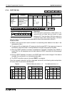
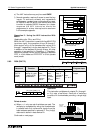
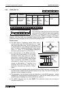
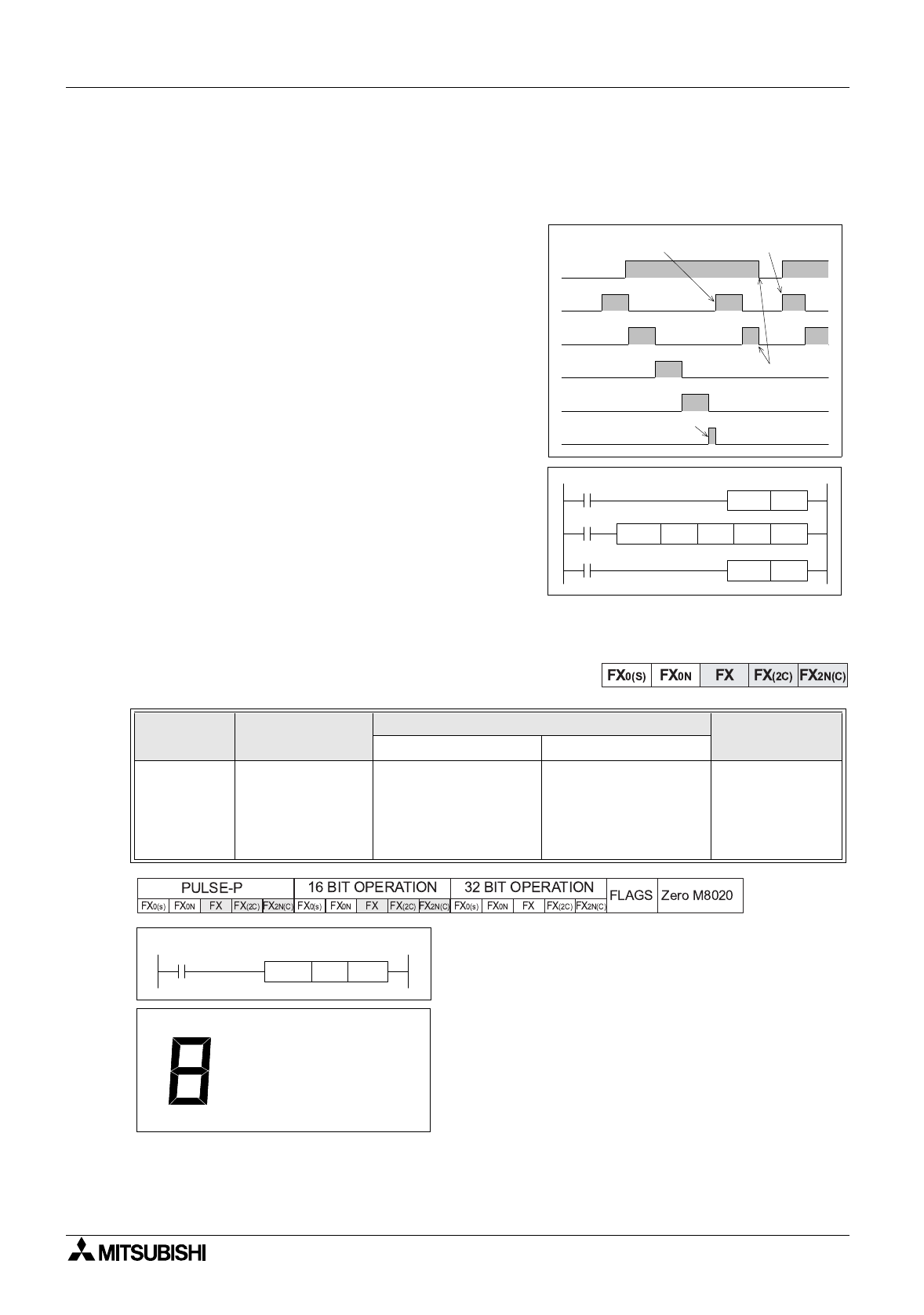
5.8.4 SEGD (FNC 73)
Operation:
A sin
g
le hexadecimal di
g
it (0 to 9, A to F)
occup
y
in
g
the lower 4 bits of source device S is
decoded into a data format used to drive a seven
se
g
ment displa
y
. A representation of the hex di
g
it
is then displa
y
ed. The decoded data is stored in
the lower 8 bits of destination device D. The upper
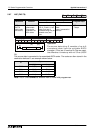
8 bits of the same device are not written to. The
dia
g
ram opposite shows the bit control of the
seven se
g
ment displa
y
. The active bits correspond
to those set to 1 in the lower 8 bits of the
destination device D.
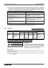
Mnemonic Function
Operands
Program steps
SD
SEGD
FNC 73
(Seven
se
g
ment
decoder)
Hex data is
decoded into a
format used to
drive seven
se
g
ment displa
y
s
K, H
KnX, KnY, KnM, KnS,
T, C, D, V, Z
Note: Uses onl
y
the
lower 4 bits
KnY, KnM, KnS,
T, C, D, V, Z
Note: The upper 8 bits
remain unchan
g
ed
SEGD,
SEGDP:
5 steps
X0
Y10
Y11
Y12
Y13
M8029
Start of repetitive operation
Restart
Suspended
operation
Cycle complete
Y 10 D 0 K 1DSW X 10
M0
M8029
X0
RST
M 0
SET
M 0
X0
D 0 K2Y0SEGD
[ D ][ S ]
B0
B1
B2
B3
B4
B5
B6
It can be seen that
B7 is NOT used.
Hence B7 of the
destination device D
will alwa
y
s be OFF,