


FX Series Programmable Controllers Assigning System Devices 9
9-6
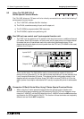
9.3 Parallel Link Adapters
The FX parallel link adapters provide a means of direct communication between two FX PLC’s.
There are two models of parallel link adapter providin
g
two different communication mediums:
a) Fiber-optic link - FX
2
-40AP
Transmission distance: 50m (164 ft)
Fiber-optic: F-OFC-M10 - len
g
th 10m (32.8 ft)
F-OFC-M30 - len
g
th 30m (98.4 ft)
F-OFC-M50 - len
g
th 50m (164 ft)
Note all of the above fiber-optic cables come with connector CA9104AP fitted.
b) Wire link (twisted pair) - FX
2
-40AW
Transmission distance: 10m (32.8 ft)
Connect like terminals to
g
ether, i.e [SA] on unit 1 to [SA] on unit 2.
Repeat for [SB] and [SG]. Finall
y
also connect the [SG] terminal of each unit to the [SG]
terminal of the local FX PLC.
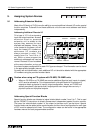
Special System Devices:
• M8070 - When this is ON the FX PLC is desi
g
nated ‘Master’.
M8071 - When this is ON the FX PLC is desi
g
nated ‘Slave’.
M8072 - When this is ON there is communication between stations.
M8073 - When this is ON there is a ‘Master/Slave’ desi
g
nation error.
M8063 - When this is on there is a link error - see error tables for further details
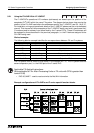
Applicable FX Applied Instructions:
• FNC 81, PRUN - Identifies which input devices are used in the data exchan
g
e.
Transmission Devices:
Master Slave, Slave Master
Bit devices -100 points Bit devices - 100 points
(M800 to 899) (M900 to 999)
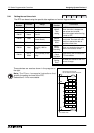
Word devices - 10 points Word devices - 10 points
(D490 to 499) (D500 to 509)
Communication Time:
• 70 msec + (master and slave station c
y
cle times)
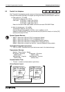
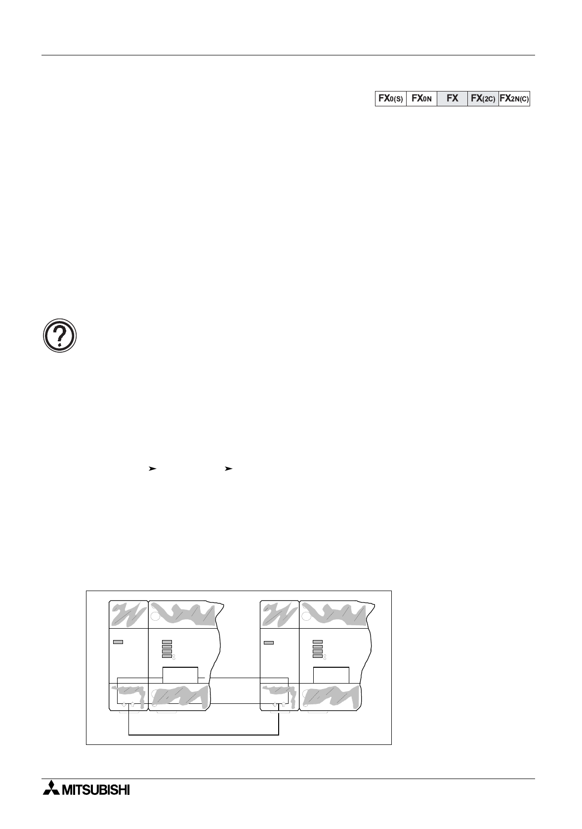
General System Layout:
POWER
MELSEC FX-48MR
RUN
BATT.V
PROG-E
CPU-E
MITSUBISHI
POWER
FX -40AP2
TR
RUN
T/R
TXD
RXD
POWER
MELSEC FX-48MR
RUN
BATT.V
PROG-E
CPU-E
MITSUBISHI
POWER
FX -40AP2
TR
RUN
T/R
TXD
RXD