


FX Series Programmable Controllers Devices in Detail 4
4-24
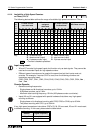
4.11.2 Availability of High Speed Counters on
FX
0
, FX
0S
and FX
0N
PLC’s
The followin
g
device table outlines the ran
g
e of available hi
g
h speed counters on both the FX
0
,
FX
0S
and the FX
0N
;
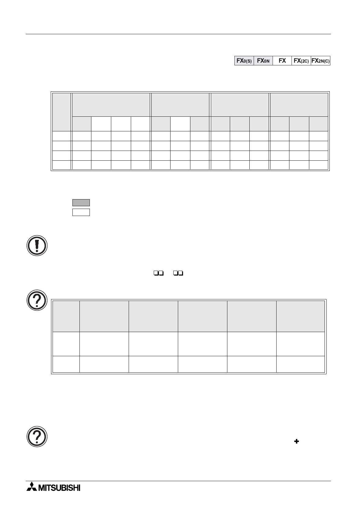
Ke
y
:
U
- up counter input
D
- down counter input
R
- reset counter (input)
S
- start counter (input)
A
- A phase counter input
B
- B phase counter input
- Counter is backed up /latched on both FX
0
, FX
0S
and FX
0N
- Counter is backed up /latched on FX
0N
onl
y
(FX
0
, FX
0S
has no backup/latch on this device)
Input assignment:
• Different t
y
pes of counters can be used at the same time but their inputs must not coin-
cide. Inputs X0 to X3 cannot be used for more than one counter. For example, if C251 is
used the followin
g
counters and instructions cannot be used; C235, C236, C241, C244,
C247, C249, C252, C254, I0 , I1 .
Counter speeds and operational rules:
• All inputs identified are 5 kHz inputs.
•Onl
y
one 2 phase or A/B phase counter should be operated at an
y
one time.
•A hi
g
h speed counter specified in an applied instruction ma
y
not be modified b
y
V or Z
indexes.
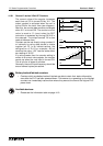
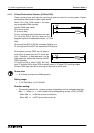
Calculating the maximum combined counting speed on FX0S:
This is calculated as follows:
(2 phase counter speed
x number of counted ed
g
es)
(the sum of the speeds of the active 1 phase counters).
I
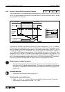
N
P
U
T
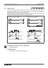
1 Phase counter
user start/reset
1 Phase counter
assigned
start/reset
2 Phase counter
bi-directional
A/B Phase counter
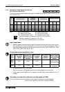
C235 C236 C237 C238 C241 C242 C244 C246 C247 C249 C251 C252 C254
X0
U/D U/D U/D U U U A A A
X1
U/D R RDDDBBB
X2
U/D U/D RR RR
X3
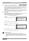
U/D R S S S
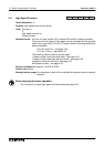
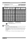
Unit
type
Max. 1 phase
counting
speed
Sum of the
speeds of the
active 1 phase
counters
Max. 2 phase
counting
speed
Max. number of
2 phase
counters
Max. combined
sum of 1 and 2
phase counting
speeds
FX
0
,
FX
0N
5kHz
≤
5kHz 2 kHz 1
1 phase and 2
phase counters
cannot be mixed
FX
0S
7kHz
≤
14kHz 2 kHz 1
≤
14kHz see
note below
C235
C236