


FX Series Programmable Controllers Devices in Detail 4
4-32
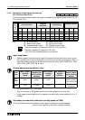
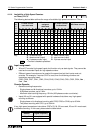
4.11.8 A/B Phase Counters (C252 to C255)
With these counters onl
y
the input identified in the previous hi
g
h speed counter tables can be
used for countin
g
. The countin
g
performed b
y
these devices is independent of the pro
g
ram
c
y
cle (scan) time. Dependin
g
on the counter used, start, reset and other associated inputs are
automaticall
y
allocated.
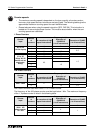
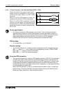
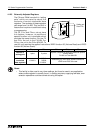
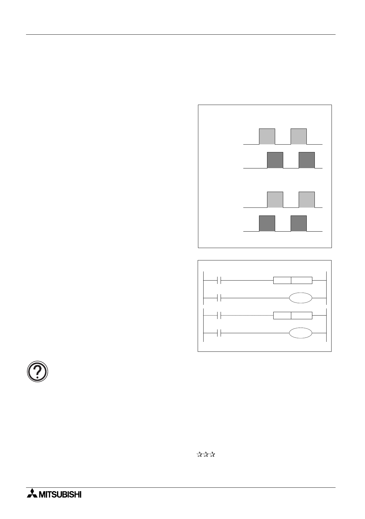
The A phase, B phase input si
g
nal not onl
y
provide the counted si
g
nals but their
relationship to each other will also dictate the
counted direction.
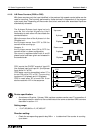
While the wave form of the A phase is in the
ON state and...
the B phase moves from OFF to ON the
counter will be countin
g
up.
However, if...
the B phase moves from ON to OFF the
counter will be in a down confi
g
uration.
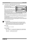
One count is re
g
istered after both A and B
phase inputs have been
g
iven and released in
the correct order.
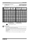
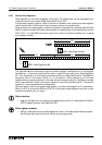
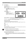
C251 counts the ON/OFF events of input X0
(the A phase input) and input X1 (the B phase
input) while X11 is ON.
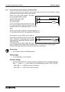
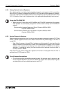
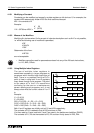
C255 starts countin
g
immediatel
y
when X7 is
turned ON while X13 is ON. The countin
g
inputs are X3 (A phase) and X4 (B phase).
C255 is reset when X5 is turned ON. It can
also be reset with X12 in the sequence.
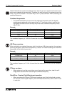
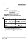
Device specification:
• A maximum of 2 points - 2 phase, 32bit, up/down counters can be used. The operation of
the output contact in relation to the counted data is the same as standard 32bit counters
described in section 4.11.
Setting range:
• -2,147,483,648 to +2,147,483,647
Direction setting:
• Check the correspondin
g
special rela
y
M8 to determine if the counter is countin
g
up or down.
A-phase
B-phase
A-phase
B-phase
Up-count
Down-count
X11
K1234
C251RST
X10
X13
D0
C255RST
X12
C251
C255