


FX Series Programmable Controllers Assigning System Devices 9
9-3
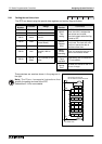
9.2.1 Using the FX
2
-24EI With A F-16NP/NT
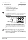
The F-16NP/NT’s operational I/O numbers (addresses) are based upon the position of the
associated FX
2
-24EI within the users FX s
y
stem. The dia
g
ram below shows how movin
g
the
position of the FX
2
-24EI used alters the addresses used b
y
the F-16NP/NT, see EX. 1A to 1C.
For installation, wirin
g
and operational details of the F-16NP/NT please see the units dedicated
manual. That manual will show examples of the F-16NP/NT bein
g
used and in each case the I/
O numbers used to address it are those fixed b
y
the F series PLC’s. These I/O addresses will
be replaced b
y
those described in the previous para
g
raph, i.e. the FX devices assi
g
ned to the
FX
2
-24EI bein
g
used.
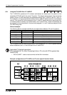
Worked example:
The followin
g
tabular example identifies the correspondence between FX and F
2
s
y
stems.
The FX s
y
stem used is similar to that shown in the dia
g
ram EX. 1C. The F
2
s
y
stem uses the
second expansion port, i.e. the X400 port of the F series PLC.
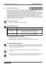
Applicable FX Applied Instructions:
(Not applicable to FX
2C
Main Processin
g
Units or FX units with CPU’s
g
reater than
version 3.06)
• FNC 90, MNET - used to read and write the Net Mini information
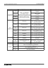
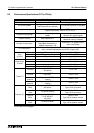
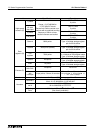
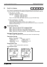
Example configurations of FX
2
-24EI’s and F series special function blocks
FX System Setup F2 System Setup Remark
X5
4
X41
4
Input data correct
X5
5
X41
5
Input data incorrect
X5
6
X41
6
Output data correct
X5
7
X41
7
Output data incorrect
X6
0
to X6
7
X42
0
to X42
7
Input to PLC
Y4
0
to Y4
7
Y440 to Y44
7
Output from PLC