


FX Series Programmable Controllers Points Of Technique 10
10-10
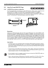
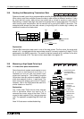
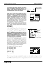
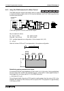
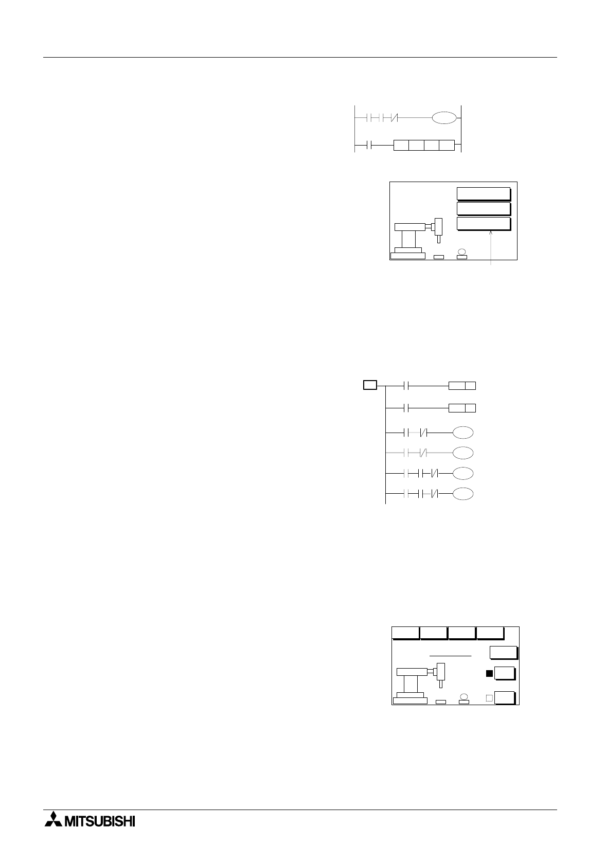
This example uses the IST instruction (FNC 60) to
control the operation mode of the robot arm. The
pro
g
ram shown opposite identifies how the IST
instruction is written into the main pro
g
ram.
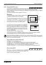
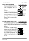
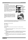
When the IST instruction is used there are 5
selectable modes which access three separate
pro
g
rams. This example has the followin
g
pro
g
rams associated with its modes. Each mode is
selected throu
g
h the FX-40DU-TK. The screen
shown opposite is the initial mode menu. Each of
the menu options causes a screen
j
ump to the
selected mode. Menu options 1 and 3 also set ON
auxiliar
y
devices M30 and M31 respectivel
y
.
The active bits then tri
gg
er a screen chan
g
e to the
selected mode. Please note 'Automatic' has three
further modes which are selected from a followin
g
screen/displa
y
.
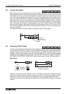
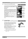
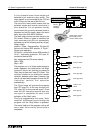
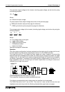
Manual Mode:
In this mode ALL operations of the robot arm are
controlled b
y
the operator. An operation or
movement is selected b
y
pressin
g
the
correspondin
g
option on the DUs screen (see
below). These options then tri
gg
er DU SWITCH
ob
j
ects which drive associated auxiliar
y
rela
y
s
within the pro
g
rammable controller. The SWITCH
ob
j
ects should be set to momentar
y
so that the
y
onl
y
operate when the ke
y
is pressed.
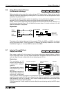
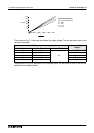
The status of the clampin
g
action could be
identified b
y
two INDICATOR (SCR) functions on
the DU unit. The
y
could be monitorin
g
the ON and
OFF status of the clamp output Y1. Hence, when
the clamp was ON a sin
g
le black box opposite the
ON button could appear. When the clamp is OFF
the box would appear in front of the OFF button. At
an
y
one time onl
y
one box would be active.
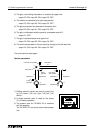
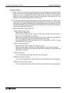
Ke
y
assi
g
nment for DU screen opposite:
Up = M15 Down = M20
Left = M16 Ri
g
ht = M21
Clamp ON = M22
Clamp OFF = M17
Menu = reset M30
Once manual operation is completed the operator can return to the main mode selection
screen b
y
touchin
g
the 'Menu' ke
y
. This causes the manual mode bit fla
g
, M30, to be reset.
Once M30 is reset the DU screen then chan
g
es back to the desired mode selection screen.
X4
X2
Y1
M8000
IST M30 S27S20
M8044
When all conditions
are met robot grip is
at zero point -
M8044 = ON
IST control - setup
Mode Selection
3. Z Return
AB
1. Manual
2. Automatic
Touch screen keys
An example DU screen design
M22
M17
S0
M15 Y0
M20
Y2
Y3
M16
X2
Y4
M21
X2
SET
Y1
RST
Y1
Y2
Y0
Y4
Y3
Clamp is active
Clamp is not
active
Move grip up
Move grip down
Move grip left
Move grip right
Manual Mode
AB
Up
Clamp
Down Left Right
OFF
ON
Menu