


FX Series Programmable Controlers Applied Instructions 5
5-113
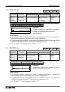
c) Operand D
2
stores the F
2
-32RM status information.
d) For more information please see pa
g
e 9-4.
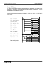
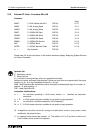
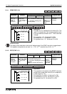
5.10.5 RMMR (FNC 94)
Operation:
This instruction sends output disable data to an F
2
-
32RM pro
g
rammable CAM switch from an FX
PLC.
The head address I/O numbers for both S
2
and Dare determined b
y
the position of the FX
2
-
24EI (connected to the F
2
-32RM) within the FX PLC’s expansion chain.
The operand S
1
is the head address of either 16 or 32 source bits. The source bits map directl
y
over F
2
-32RM outputs Y0 to Y37 (numbered in octal)
When a source device is turned ON at the FX PLC the F
2
-32RMs associated devices is
disabled.
For more information please see pa
g
e 9-4.
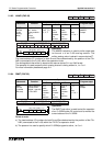
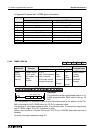
Status of bit device
D
2
+m
ON OFF
D
2+0
BANK 1 (pro
g
ram 1) selected BANK 0 (pro
g
ram 0) selected
D
2+1
- Normall
y
OFF
D
2+2
START STOP
D
2+3
1.0 de
g
ree steps 0.5 de
g
ree steps
D
2+4
Normall
y
ON -
D
2+5
Clockwise operation (CW) Counter-clockwise operation (CCW)
D
2+6
Normal operation - No error Hardware Error
D
2+7
Normal operation - No error Software Error
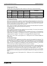
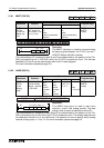
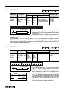
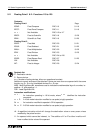
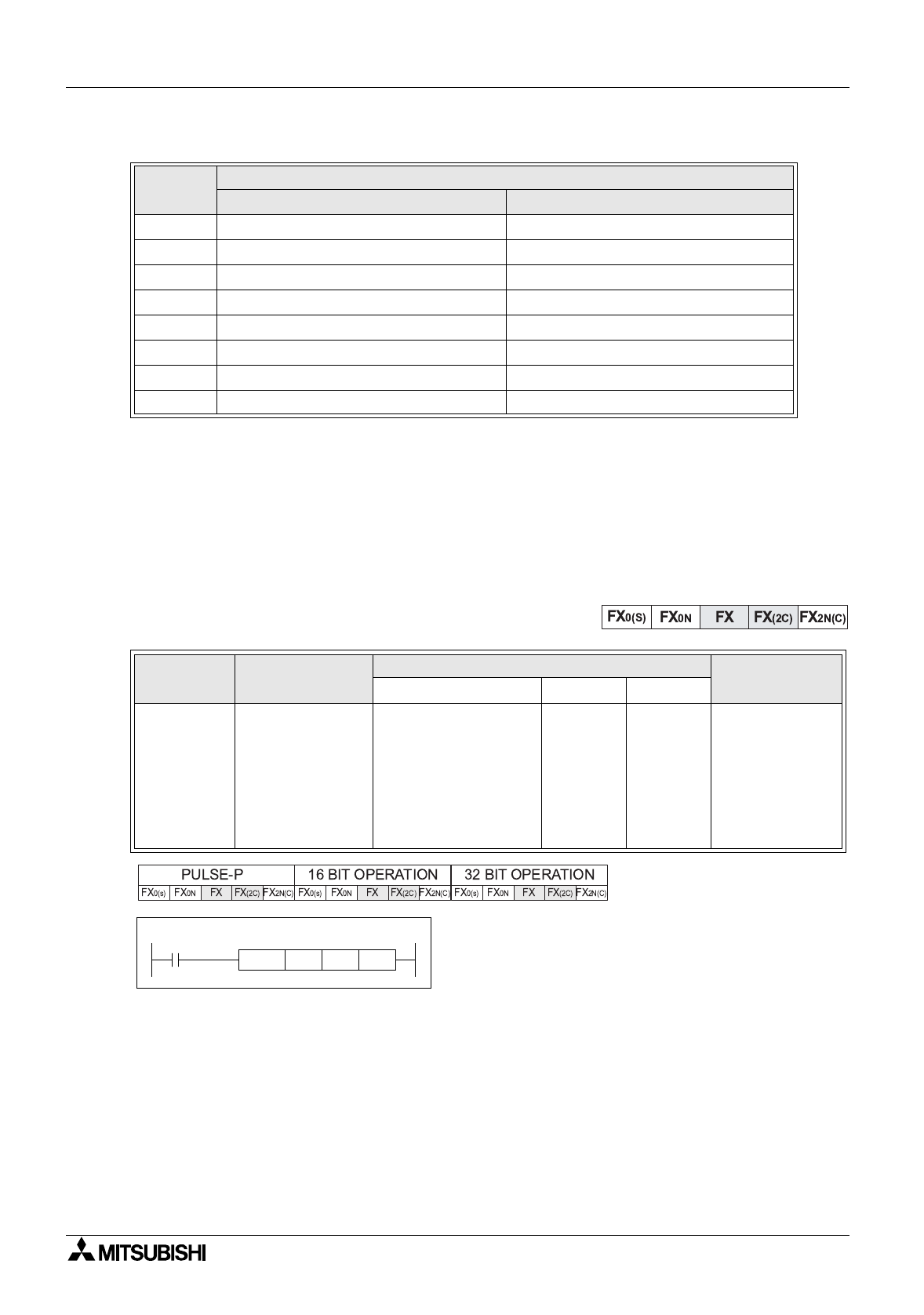
Mnemonic Function
Operands
Program steps
S
1
S
2
D
RMWR
FNC 94
(
F
2
-32RM
RM write)
Disables outputs
of the F series
CAM module -use
with an
FX
2
-24EI
Y, M , S
Note: 16 bit operation
uses 16 devices,
32 bit mode uses 32
consecutive devices.
X
Note:
uses 8
consecutiv
e
devices
Y
Note:
uses 8
consecutiv
e
devices
RMWR,RMWRP
:7 steps
DRMWR,
DRMWRP:
13 steps
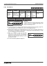
X0
X40 Y30
[ D ]
RMWR
[ S2 ]
M500
[ S1 ]