


FX Series Programmable Controlers Applied Instructions 5
5-54
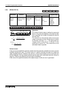
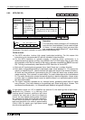
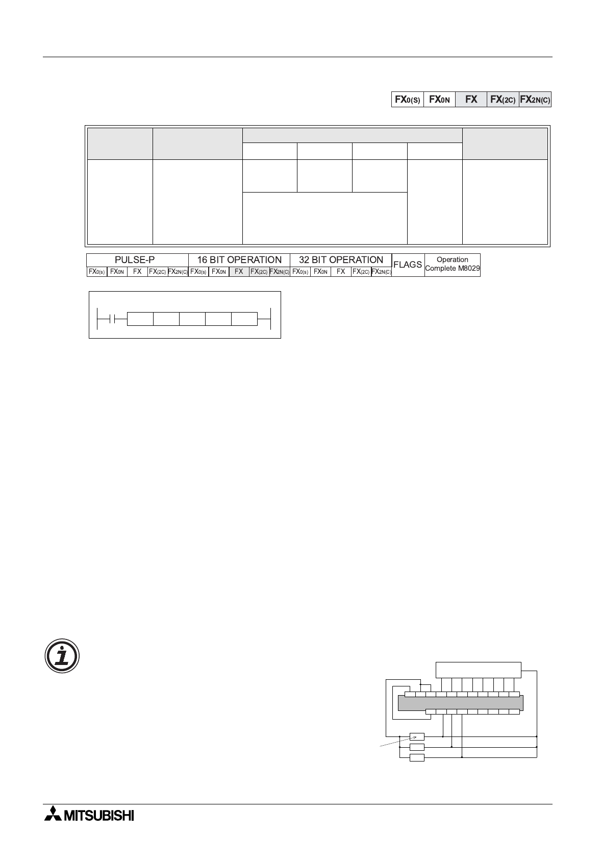
5.6.3 MTR (FNC 52)
Operation:
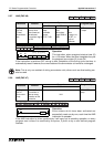
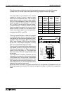
This instruction allows a selection of 8 consecutive
input devices (head address S) to be used multiple
(n) times, i.e. each ph
y
sical input has more than
one, separate and quite different (D
1
) si
g
nal bein
g
processed. The result is stored in a matrix-table (head address D
2
).
Points to note:
a) The MTR instruction involves hi
g
h speed input/output switchin
g
. For this reason this
instruction is onl
y
recommended for use with transistor output modules.
b) For the MTR instruction to operate correctl
y
, it must be driven continuousl
y
. It is
recommended that special auxiliar
y
rela
y
M8000, the PLC RUN status fla
g
, is used. After
the completion of the first full readin
g
of the matrix, operation complete fla
g
M8029 is turned
ON. This fla
g
is automaticall
y
reset when the MTR instruction is turned OFF.
c) Each set of 8 input si
g
nals are
g
rouped into a ‘bank’ (there are n number of banks).
d) Each bank is tri
gg
ered/selected b
y
a dedicated output (head address D
1
). This means the
quantit
y
of outputs from D
1
, used to achieve the matrix are equal to the number of banks n.
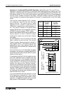
As there are now additional inputs enterin
g
the PLC these will each have a status which
needs recordin
g
. This is stored in a matrix-table. The matrix-table starts at the head address
D
2
. The matrix construction mimics the same 8 si
g
nal b
y
n bank confi
g
uration. Hence, when
a certain input in a selected bank is read, its status is stored in an equivalent position within
the result matrix-table.
e) The matrix instruction operates on an interrupt format, processin
g
each bank of inputs
ever
y
20msec. This time is based on the selected input filters bein
g
set at 10msec. This
wouldresultinan8bankmatrix, i.e. 64inputs(8inputs´8banks) bein
g
readin160msec.
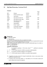
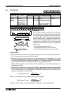
Mnemonic Function
Operands
Program steps
S
D
1
D
2
n
MTR
FNC 52
(Input
matrix)
Multiplexes a
bank of inputs
into a number of
sets of devices.
Can onl
y
be used
ONCE
X
Y
Y, M, S
K, H,
Note:
n=2 to 8
MTR: 9 steps
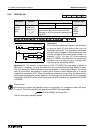
Note:
These operands should alwa
y
s be
a multiple of 10, i.e. 00, 10, 20, 30
etc.
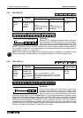
M8000
M 30 K 3
[ S ] [ D2 ]
Y 20
[ n ]
X 10MTR
[ D1 ]
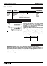
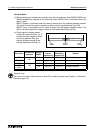
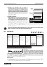
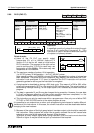
If hi
g
h speed inputs (ex. X0) is specified for operand S, the readin
g
time of each bank
becomes onl
y
10msec, i.e. a halvin
g
of the
readin
g
speed. However, additional pull down
resistors are required on the drive outputs to
ensure the hi
g
h speed readin
g
does not detect
an
y
residual currents from the last operation.
These should be placed in parallel to the input
bank and should be of a value of approximatel
y
3.3k
Ω
, 0.5W. For easier use, hi
g
h speed inputs
should not be specified at S.
Y42Y43Y44Y45Y46Y47+V Y40Y41
X0 X1 X2 X3 X4 X5 X6 X7
24V 0V S/S
Matrix device
Pull down
resistors